Sign In
Upload
Manuals
Brands
Bosch Manuals
Measuring Instruments
BEA 350
Bosch BEA 350 Manuals
Manuals and User Guides for Bosch BEA 350. We have
1
Bosch BEA 350 manual available for free PDF download: Repair Instructions
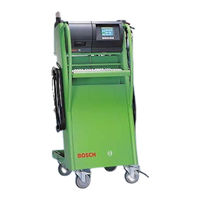
Bosch BEA 350 Repair Instructions (103 pages)
Emissions Analysis
Brand:
Bosch
| Category:
Measuring Instruments
| Size: 2.49 MB
Table of Contents
Table of Contents
2
Important Information
2
1 Important Information
4
Compulsory Calibration
4
2 Testing Equipment and Settings for the Service Software
5
Testing Equipment
5
Calibrating Gases (with Manufacturer's Certificate)
5
Settings for the Service Software
6
Setting the Interface for the Service Program
6
Service Software Language Selection
6
Language Selection for RTM
7
Smoke Opacity Module Service Software
7
3 Brief Description of Unit Functions and Servicing the Unit
8
Exhaust-Gas Analyzer Module
8
Analyzer Part (HC, CO and CO 2 Measurement)
8
System Calibration
8
Self-Test
8
Adjustment
8
Measuring Channels)
8
Measuring Channel
8
Compensation of Pressure Influence
8
Compensation of Temperature Influence
8
Parameterization
9
Corrected CO Concentration
9
Filtration
9
Principle of Filtration
9
Servicing the Unit
9
Half-Yearly Service
9
Yearly Service
9
4 Checking the AMM Exhaust-Gas Analyzer Module
11
Read Operating Mode
11
Leakage Test
11
Read Measurement Values
13
Read Parameters
13
Write Parameters
13
Country-Specific Settings
14
Lambda Calculation on
14
Lambda Calculation off
15
Calculation on
15
CO Vrai
15
Sensor Available
16
Sensor Not Available
16
Identification
17
Test Functions
17
Pump on
18
Pump off
18
Install New O
18
Measurement
18
Readjustment with Test Gas
20
Analysis Mode
21
Barometric Sensor
21
Maintenance (Service Date)
22
Read Adjustment Data
22
Adjustment Functions
23
Reset
23
Error Inquiry
23
NO-Sensor
24
Read NO-Sensor
24
Set NO-Sensor
24
NO-Measurement
24
Mounting a New NO-Sensor
27
Readjustment with Test Gas
29
Read Calibration Data
30
Calibration Interval Setting
30
Calibration Sequence Setting
30
Checking Opacimeter RTM 430
31
5 Checking the PCB and Periphery of the BEA Control Module
32
Checking the Interface for DTM
32
Checking the Interface for RTM
33
Checking the Interface for AMM
33
Checking the Interface for OBD
34
Checking the Interface for OBD Extern
35
Loop Test
35
OBD Error Messages
36
Testing 26-Pin Interface for OBD External (with CAN Protocol)
37
Checking the Interface for the Data Terminal (Not for BEA-Euro)
38
Checking the Hard Disk
38
Checking the Floppy Disk Drive
39
Checking the Internal Printer
39
Checking the External Printer
40
Setting the Date and Time
40
Video RAM Test
40
Display Test
41
Display Test Geometry Image
41
Display Test Full Screen All White
41
Display Test Full Screen All Black
42
Checking the Foil Keypad
42
Checking the PC Keyboard
42
Checking the Remote Control
43
Checking the Test Calibration Switch for Customer Service
43
Reading out the Error List
43
Download Systemsoft
43
6 Checking the Engine-Speed and Temperature Measuring Module (DTM)
45
Checking Oil Temperature and Engine Speed in Diesel Diagnosis
45
Terminal Diagram of Connection Cable for
46
Terminal Diagram of Temperature Sensor
46
Checking Oil Temperature and Engine Speed in Petrol Diagnosis
48
Terminal Diagram of Inductive Clip-On Trigger Sensor
48
Checking V-Lambda
49
Terminal Diagram of V-Lambda Cable
49
Checking the Ignition Point and Dwell Angle
49
Checking the Dwell Angle
50
Terminal Diagram of Timing Light
51
Terminal Diagram of TD/TN Connection Cable
51
7 Technical Information
52
Exhaust-Gas Analysis in Petrol-Driven Vehicles
52
Opacity Measurement
52
Engine Measurement System TDM
52
Temperature Measurement
52
RPM Measurement, Petrol-Driven Vehicles
52
RPM Measurement, Diesel Vehicles
52
Multiple Measurements
53
Ignition Point/Timing
53
Dwell Angle
53
Start of Delivery/Injection Timing
53
8 Trouble-Shooting by Message Number
54
Explanations on Reference Numbers
54
General Messages
54
Messages about Boot Test Functions
55
Messages about Software Installation Functions
56
Messages about Printing Functions
57
Messages about Hardware Test Functions
57
Messages about Opacimeter RTM
58
Messages about EAM Exhaust-Gas Analyzer Module
59
Reference Numbers When Downloading DTM Firmware
60
Reference Messages on OBD Printed Circuit Board
61
Reference Numbers for Errors in "Fatal" Group
61
Reference Numbers for Errors in "Status Error" Group
61
Reference Numbers for Errors in "Download" Group
61
Reference Numbers for Errors in „Communication Error" Group
62
Reference Numbers in Combination with Awn.modul
62
Malfunction Messages for Testing OBD Printed Circuit Board with KTS115PC Program
63
Error Messages for "SDTEST
63
Error Messages for "DLCTEST
63
Error Messages for "LBCTEST
64
Error Messages for "CANTEST
64
9 Adjustment Functions
65
Setting the Maintenance Interval
65
Setting the Calibration Interval
66
Setting the Calibration Gas Components
66
Setting the Calibration Sequenz
66
Setting the Leakage Test Interval
67
Setting the HC Test
67
Setting CO
67
National Regulation Settings
68
Download
68
10 Repairs
69
Adjusting Mains Voltage for Toroidal Mains Transformer
69
AC / DC Voltage Supply to Control Module PCB
69
Block Circuit Diagram of Voltage Supply
70
View of Equipment Side of Control Module PCB
71
Visual Inspection of Measuring Bank of Exhaust-Gas Analyzer Module
72
Electrical Test of Measuring Bank of Exhaust-Gas Analyzer Module
72
Leak Test of Measuring Bank
72
Cleaning the Lamp Reflector
73
Cleaning the Analysis Chambers and Windows
74
Replacing the Measuring Bank
75
Install New O Sensor
75
Checking Cross Sensitivity
77
Checking the Pump Suction Power
77
Replacing the Pump
78
Checking the Pressure Sensor
78
Checking the Response Time of the Pressure Sensor
78
Replacing the Pressure Sensor
79
Replacing the Water Separator
79
Replacing the Solenoid Valve
80
Replacing the no Sensor
80
Replacing the Internal Printer
81
Replacing the Printing Mechanism
81
Replacing the Controller PCB
81
Replacing the Disk Drive
82
Replacing the TFT Display
82
Replacing the Membrane Keypad
82
Replacing the Receiver Diode for the Remote Control
83
Replacing the Control Module PCB
84
Replacing the Temperature and RPM PCB
84
Replacing the Control-Power Transformer
84
Replacing the OBD Circuit Board
85
Replacing AWN Printed Circuit Board
86
Replacing the Power Switch
87
Replacing the Battery
87
Replacing Hard Disc
87
11 BEA Test Software OS9
88
Hard Disk
88
Identification
88
Testing
88
Formatting
89
Flash
89
Floppy Disk
90
Language
90
12 Overview
91
Electrical Wiring (Siemens Analysis Chamber)
91
Circuit Diagram (Siemens Analysis Chamber)
92
Wiring Diagram (Siemens Analysis Chamber)
93
Hosing (Siemens Analysis Chamber)
94
Gas Circuit Diagram (Siemens Analysis Chamber)
95
Electrical Wiring (Andros Analysis Chamber)
96
Circuit Diagram (Andros Analysis Chamber)
97
Wiring Diagram (Andros Analysis Chamber)
98
Hosing (Andros Analysis Chamber)
99
Gas Circuit Diagram (Andros Analysis Chamber)
100
Overview of Components
101
Advertisement
Advertisement
Related Products
Bosch BEA 060
Bosch BEA 070
Bosch BEA 810
Bosch BEA 840
Bosch BEA 850
Bosch BEA 040
Bosch BEA 550
Bosch BEA 065 (UNI)
Bosch BEA 065
Bosch BEA 055
Bosch Categories
Dishwasher
Washer
Oven
Power Tool
Dryer
More Bosch Manuals
Login
Sign In
OR
Sign in with Facebook
Sign in with Google
Upload manual
Upload from disk
Upload from URL