Table of Contents
Advertisement
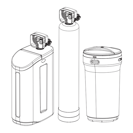
EconoFlo
Water Softener
1. Page 20 of this manual contains important maintenance procedures for the continued proper
operation of your unit. These MUST be performed regularly for your warranty to remain valid.
2. Read all instructions carefully before operation.
3. Avoid pinched o-rings during installation by applying NSF certified lubricant to all seals (provided with install kit).
4. This system is not intended for treating water that is microbiologically unsafe or of unknown quality without
adequate disinfection before or after the system.
Canada West
Canada East
855 Park St., Unit 1
490 Pinebush Rd., Unit 1
Regina, SK S4N 6M1
Cambridge, ON N1T 0A5
U.S.A.
56 Lightcap Rd.
9760 Mayflower Park Drive,
Pottstown, PA 19464
Suite 110
Carmel, IN 46032
IAPMO R & T Certified
against CSA B483.1
4655 McDowell Rd. W
Phoenix, AZ 85035
Advertisement
Table of Contents

Related Manuals for NOVO EFT30


Summary of Contents for NOVO EFT30
- Page 1 EconoFlo IAPMO R & T Certified against CSA B483.1 Water Softener 1. Page 20 of this manual contains important maintenance procedures for the continued proper operation of your unit. These MUST be performed regularly for your warranty to remain valid. 2.
-
Page 2: Table Of Contents
READ THIS PAGE FIRST BEFORE STARTING INSTALLATION HOW YOUR WATER CONDITIONER WORKS SPECIFICATIONS SPECIFICATION / SYSTEM DIMENSIONS BRINE TANK DIMENSIONS INSTALLATION UNPACKING / INSPECTION OF TWIN TANK MODEL UNPACKING / INSPECTION OF CABINET MODEL BEFORE INSTALLATION PREPARATIONS PREPARATIONS / INSTALLATION STEPS INSTALLING BRINE TANK INSTALLATION OPERATION... -
Page 3: Read This Page First
READ THIS PAGE FIRST BEFORE STARTING INSTALLATION Read this manual thoroughly to become familiar with the Avoid pinched o-rings during installation by applying device and its capabilities before installing or operating your (provided with install kit) NSF certified lubricant to all seals. Water Filter. -
Page 4: How Your Water Conditioner Works
Backwash Number Number Size (Inches) (cu.ft.) Size Inches (WXDXH) (lbs) Weight (lbs) @ 10 lbs/cu ft @ 3 lbs/cu ft Setting USGPM USGPM EFC20 2117 19,875 16,500 10,500 9X35 0.75 13.8 X 23.6 X 34.5 EFC30 2118 26,500 22,000 14,000 10X35 13.8 X 23.6 X 34.5... -
Page 5: Specification / System Dimensions
B (Inches) must be operated on pressures Do not use peak flow rate for commercial applications 35” 9" EFC20 between 30 psi to 125 psi. If the water or for a continuous rate when treated water supplies are EFC30 35”... -
Page 6: Brine Tank Dimensions
BRINE TANK DIMENSIONS Model Color Liquid Volume Tank Dimensions 5 Pack Carton Salt Capacity (inches) Dimensions (inches) US Gal Liters L x W x H L x W x H Brine Tanks BTR-100 Vanilla 29.5 111.5 18.1 x 34.7 18.9 x 18.9 x 65.6 270.0 122.2 BTR-145... -
Page 7: Unpacking / Inspection Of Twin Tank Model
UNPACKING / INSPECTION OF TWIN TANK MODEL Be sure to check the entire unit for any shipping damage or parts loss. Also note damage to the shipping cartons. Contact the transportation company for all damage and loss claims. The manufacturer is not responsible for damages in transit. Small parts, needed to install the Softener, are in a parts box. - Page 8 For Models EFT60 and EFT90 the media and Control Valve is packaged separately in carton and bags What is included with EFT60 and EFT90 models? There are 7 Red clips. Please check to make sure 2. Control Valve 1. Tank (Models 30 and 40 will get an Adapter and Oring attached to the tank) you have all of them.
-
Page 9: Unpacking / Inspection Of Cabinet Model
UNPACKING / INSPECTION OF CABINET MODEL 1. Cabinet with Valve attached - EFC20 & EFC30 2. Parts Box 3. Owners Manual and Warranty Card 2. Parts Box 60010006 60090010 Bypass Tool 2 X 3/4” Elbow 92360 Adapter) Grease Packet 60090003 2X 1”... - Page 10 Check Valve Type and Valve Serial # The right Sticker shows the serial # of the control valve. The middle Sticker is dataplate which provides information of Serial # and Date of Manufacture of complete system. Both Serial # labels are important for troubleshooting. Please record these numbers for future use on page 21 in the maintenance section.
-
Page 11: Before Installation
BEFORE INSTALLATION NOTE Make sure you have a copy of your most recent water test results. If your water has not been tested previously you can contact All government codes and your supplier of this product to obtain a water sample bottle to be sent to one of our facilities for a free analysis. It is important regulations governing the that this product not be installed until you have this information. -
Page 12: Preparations
CAUTION! PREPARATIONS The unit should be 1. Media Installation (When Necessary). Models including and higher than 2 CF (Models 60, 90) of media are shipped with depressurized before separate media in pails or boxes. Models lower than 2 CF of media come loaded with media and this step can be skipped for new installing or replacing media installation. -
Page 13: Preparations / Installation Steps
PREPARATIONS Attaching Bypass to Valve (If required in case of replacing the control valve. The new control Clips valve comes with bypass attached) Make sure the bypass is attached well to the control valve. Connect the straight or elbow connectors to the bypass with red clips. -
Page 14: Installing Brine Tank
INSTALLING BRINE TANK Assembling Brine Tank* c) Drop the brine grid with brine well inside the d) Take the brine tube and insert the nut and plastic sleeve as brine tank such that the nut fitting faces the shown below. a) Attach the three brine grid legs to grid plate. -
Page 15: Installation
INSTALLATION Connect Softener to the HousePlumbing Any solder joints near the valve must be done before connecting any piping to the valve. Always leave at least 6” (152 mm) between the valve and joints when soldering pipes that are connected to the valve. Failure to do this could cause damage to the valve. EconoFlo Water Softener Installation Cold (Raw water) Cold (Raw water) - Page 16 INSTALLATION Connect Softener to the HousePlumbing Any solder joints near the valve must be done before connecting any piping to the valve. Always leave at least 6” (152 mm) between the valve and joints when soldering pipes that are connected to the valve. Failure to do this could cause damage to the valve. EconoFlo Cabinet Softener Installation Cold (Raw water) Cold (Raw water)
-
Page 17: Startup Instructions
STARTUP INSTRUCTIONS 2. Screen Display Familiarize with Button Configuration: 1. Connect the Transformer to the Valve Plug the 12-volt transformer into a 120 VAC 60 Hz outlet. The controller will show the TIME following on the screen - Time, 05:22 PM Date and Remaining Gallons or Days. - Page 18 STARTUP INSTRUCTIONS (CONTINUED) 4. Manually Regenerate the Valve (Continued) 4a. Open the inlet on the bypass valve slowly and allow water to enter the unit. (The outlet of the bypass should remain closed to prevent any fines or debris from entering the plumbing system.
-
Page 19: During Regeneration/Plumbing System Clean-Up
DURING REGENERATION Automatic Water Bypass The regeneration cycle lasts approximately 1.5 hours to 3.0 hours depending on the specific model, after which treated water service will be restored. During regeneration, untreated water is automatically bypassed for use in the household. Hot water should be used as little as possible during this time to prevent hard water from filling the water heater. -
Page 20: Maintenance Instructions And Schedule
MAINTENANCE INSTRUCTIONS AND SCHEDULE Service Schedule Ÿ The seals and spacers along with the piston assembly should be inspected/cleaned or replaced every year depending on the inlet water quality and water usage on clean municipal supplies every 2 - 3 years should be sufficient but the first check should be done after 1 year. See inspection and replacement of Piston assembly and seal and spacer kit, page 24. - Page 21 MAINTENANCE INSTRUCTIONS AND SCHEDULE Checking the Salt Level Check the salt level monthly. Remove the lid from the cabinet or brine tank, make sure salt level is always above the brine level. CAUTION! Add Salt to the Brine Tank Incorrect start up, water Put 40 kgs of crystal water softener salt in the brine tank.
-
Page 22: Res-Up® Feeder Installation Instructions
RES-UP FEEDER INSTALLATION ® INSTRUCTIONS (OPTIONAL) Res Up Feeders or Res Care Feeders attach to your brine tank and automatically dispense the Resin cleaner into the brine solution where it Res-up feeder cleans the resin during the regeneration cycle. 5/8" hole in brine well cap The feeder hooks onto the tube inside your brine tank and you just pour some chemical in. -
Page 23: Servicing Econoflo Valve
SERVICING ECONOFLO VALVE Before Servicing 1. Turn off water supply to conditioner : a. If the conditioner installation has a 3 valve bypass system first open the valve in the bypass line, then close the valves at the conditioner inlet & outlet. b. - Page 24 CLEAN INJECTOR ASSEMBLY 1. Remove two screws of the injector cap. 2. Pull the Injector Cap off, Remove the injector assembly, oring and screen, clean the injectors with Res Care solution, vinegar, or similar solution such as CLR. Replace the injectors , snug only do not overtighten.
-
Page 25: Replacing The Bypass And Meter Cable
REPLACING THE BYPASS AND METER CABLE Grey Meter Cable 60010267 Bypass comes with Meter 60095101 and Grey Meter Cable Step 1 Step 2* Disconnect the meter cable from Remove 2 screws and Unplug the the bypass. power from the clips from bypass. wall socket. -
Page 26: Replace Drain Line Flow Control / Replacing Pcbs
REPLACE DRAIN LINE FLOW CONTROL 1. Pull the drain line clip and remove the drain line elbow and washer 2. Clean/replace drain line washer Drain washer Clip Drain Line Elbow REPLACING PCBS Remove PCBs by removing the screws shown in the picture... -
Page 27: Parts Breakdown
PARTS BREAKDOWN Control Valve Upper Cone (18280) Distributor Bypass - 60095101 Downflow Softener Model Mineral Tank Tank # (Natural Color) Distrubutor# Valve # Media Bed # Size Softener Downflow (Single Tank) EFC/T20 9 x 35 25010028 50010005 95600 EFC/T30 10 x 35 25010043 50010005 95601... -
Page 28: Powerhead
PARTS BREAKDOWN Power head parts list Part # Description B28 60010098 Bnt65 Back Cover B27 60010658 Screw-M3×5 B26 60010050 Motor-12v/2rpm B25 60010659 Motor Mounting Plate B24 60010660 Motor Pin B23 60010054 Screw-ST3.5×13 (Hexagon with Washer) B22 60010055 Piston Stem Holder B21 60010099 Screw-ST2.9×13 (Large Wafer) -
Page 29: Valve Body
PARTS BREAKDOWN Valve Body Parts List Part # Part Description Qty 60010076 SCREW M5×16 For 165, 265, 465, 565, 665, 765 - Piston Assembly #60010027 60010075 SCREW M5×12 For 65 CC Valve - 60010645 END PLUG RETAINER Piston Assembly #60102-00 60010508 END PLUG 13001... -
Page 30: Bypass
PARTS BREAKDOWN Bypass Parts List Part # Part # Description (Water Group) (Canature) 60010267 05010108 Grey Meter Cable cc 60010006 70020007M Bypass Tool 05056212 063 Bypass Body 60010026 26010143 O-ring on Inlet and Outlet 60010019 21319011N Straight 1" NPT Inlet and Outlet 60010023 21319036N Elbow 3/4"... -
Page 31: Cabinet
PARTS BREAKDOWN Cabinet Parts List Part # Description Trim Strip Softener Cabinet(Grey) 60010361 Pressure Tank Clamp 25020019 TANK ASSY 935 NAT 25020020 TANK ASSY 1035 NAT 50010020 Distribution Assy-1035 18280 Top Cone 60095097-1 Bypass Valve Assy 765 Control Valve(Grey) 55010031 Softener Low Cover 85010132... -
Page 32: Trouble Shooting
TROUBLE SHOOTING Issue Possible Cause Possible Solution 1. No power supply. Check electrical service, fuse, etc. Unit fails to initiate a regeneration cycle. 2. Defective circuit board. Replace faulty parts. 3. Power failure. Reset time of day. 4. Defective meter. Replace turbine meter. -
Page 33: Master Programming
MASTER PROGRAMMING Familiarize with Button Configuration: Key Pad Configuration: SETTINGS - This function is to enter the basic set up information required at the time of installation. SELECT - This function is to accept the values if changed and advance to the next page in the menu. - Page 34 MASTER PROGRAMMING FACTORY OPTIONS (LEVEL II) Press UP and DOWN key Hold until you hear a beep (3 seconds). Press UP or DOWN key to change value. Press SELECT key accept change and advance to next page. SOFTENER MODE CALENDAR METER METER METER...
- Page 35 The values in this page are for illustration purpose and can be changed by the factory without notice. Please contact Customer Service to confirm proper settings. REG. DYS 665 ECONO FLO Programming 11/9/2018 MODELS EFC20/EFT20 EFC30/EFT30 EFT40 EFT60 EFT90 SOFTENER VALVE SOFTENER VALVE...
- Page 36 Toll-Free: 1-877-288-9888 • • • • Regina, SK Cambridge, ON Carmel, IN Pottstown PA Phoenix, AZ 54816 11/18...
Need help?
Do you have a question about the EFT30 and is the answer not in the manual?
Questions and answers