Advertisement
Technische Information
Technical Information
Information Technique
Schutzgeräte
SE-C1 und SE-C2
für Schraubenverdichter
Inhalt
1 SE-C1 und SE-C2
4 Technische Daten
5 Prinzipschaltbilder
1 SE-C1 und SE-C2
Diese optionalen Schutzgeräte über-
wachen mehrere Betriebs-Parameter
und schützen so den Verdichter über
die allgemein üblichen Kontrollfunkti-
onen hinaus.
Zusätzlich zu den Funktionen des
Standard-Schutzgeräts SE-E1 (Über-
wachung von Motor- und Druckgas-
Temperatur, Drehrichtung und Pha-
senausfall vgl. ST-120) überwachen
SE-C1 und SE-C2 noch die Phasen-
symetrie, Schalthäufigkeit und Ölver-
sorgung. Sie ersetzen die Schutzgerä-
te SE-E1, INT389R sowie OFC bei
HS- und OS-Schrauben.
Das SE-C1 ist für die CSH- und die
HS.64/74-Schrauben und das SE-C2
speziell für HS.85-Verdichter konzi-
piert.
Die Schutzgeräte arbeiten über einen
großen Spannungsbereich. Dies er-
laubt den Einsatz in nahezu allen
Stromnetzen (50 und 60 Hz) sowie
eine Überwachung von Verdichtern im
Frequenzumrichter-Betrieb. Ein Vor-
schaltgerät für den Betrieb von Son-
dermotoren für 575 und 690 V ist
nicht erforderlich.
Protection Devices
SE-C1 and SE-C2
for Screw Compressors
Content
1 SE-C1 and SE-C2
2 Monitoring functions
5 Schematic wiring diagrams
1 SE-C1 and SE-C2
These optional protection devices
monitor several operational parame-
ters to protect the compressor beyond
the standard control functions.
SE-C1 and SE-C2 offer all functionali-
ty provided by the standard protection
device SE-E1 (monitoring of motor
and discharge gas temperatures, rota-
tion direction and phase failure, see
ST-120), but also monitor phase sym-
metry, switching frequencies and oil
supply. They replace the protection
devices SE-E1, INT389R and OFC for
HS and OS screws.
The SE-C1 is designed for CSH and
HS.64/74 screws, the SE-C2 especial-
ly for the HS.85 compressors.
The protection devices work over a
large voltage range. This allows the
use in nearly all power supply sys-
tems (50 and 60 Hz), as well as for
monitoring compressors with frequen-
cy inverters. A step down resistor
device for the operation of special
motors for 575 and 690 V is not
required.
Dispositifs de protection
SE-C1 et SE-C2
pour les compresseurs à vis
Sommaire
1 SE-C1 et SE-C2
2 Fonctions de contrôle
3 Fonctions et pannes signalées
1 SE-C1 et SE-C2
Ces dispositifs de protection optionnaux
contrôlent plusieurs paramètres de fonc-
tionnement et protègent aussi le com-
presseur au-delà des fonctions de contrô-
le usuelles.
En plus des fonctions du dispositif de pro-
tection standard SE-E1 (contrôle de la
température moteur et du gaz de refoule-
ment, sens de rotation et défaut de
phase, voir ST-120) sont supplémentés
par des fonctions des SE-C1et SE-C2:
surveillance de la symétrie des phases,
de la fréquence d'enclenchement et d'ali-
mentation en huile. Ils remplacent les dis-
positifs de protection SE-E1, INT389R et
OFC pour des vis HS et OS.
Le SE-C1 a été conçu pour les vis CSH
et HS.64/74, le SE-C2 spécialement pour
les compresseurs HS.85.
Les dispositifs de protection couvrent une
large plage de tensions. Ils sont donc uti-
lisables sur pratiquement tous les
réseaux électriques (50 et 60 Hz) ainsi
que pour le contrôle des compresseurs
avec convertisseur de fréquences. Un
transformateur pour le fonctionnement
des moteurs spéciaux pour 575 et 690 V
n'est pas nécessaire.
ST-121-2
Advertisement

Related Manuals for Bitzer SE-C2


Summarization of Contents
Introduction to Bitzer SE-C1 and SE-C2 Protection Devices
SE-C1 and SE-C2 Overview
Optional protection devices monitor parameters beyond standard functions for compressors.
Key Monitoring Functions
Overview of the various monitoring functions provided by SE-C1 and SE-C2.
Functional and Failure Messages
Details on functional and failure messages indicated by the protection devices.
Technical Data and Schematics Summary
Summary of technical data and principle wiring diagrams for the protection devices.
Detailed Monitoring Functions
Temperature Monitoring
Monitoring of motor, oil, and discharge gas temperatures via PTC sensors.
PTC Measuring Circuit Integrity
Monitoring of the PTC measuring circuit for short circuits or cable failures.
Advanced Compressor Monitoring
Phase Failure, Asymmetry, and Rotation Checks
Monitoring phase failure, asymmetry, and rotation direction for compressor protection.
Maximum Switching Frequency Control
Monitoring and limiting the maximum switching frequency of the compressor.
Oil Level and Supply Monitoring
Monitoring of oil level in CSH compressors and the oil supply.
Oil Management and Reset Procedures
Oil Supply Flow Monitoring
Monitoring the oil supply for HS screws via oil flow switch.
Oil Stop Valve Functionality
Monitoring the oil stop valve function for SE-C2 on HS.85 compressors.
Manual Resetting Protection Devices
Procedure for manual reset of the protection devices after fault clearance.
SE-C1 Electrical Wiring Diagrams
CSH Compressor Wiring
Electrical connection diagram for SE-C1 in CSH compressor terminal box.
HS.64/HS.74 Compressor Wiring
Electrical connection diagram for SE-C1 in HS.64/HS.74 compressor terminal box.
SE-C2 Electrical Wiring Diagrams
HS.85 Compressor Wiring
Electrical connection diagram for SE-C2 in HS.85 compressor terminal box.
Protection Device Signal Lamp Functions
H1/H2: Pause Time Indication
H1 off, H2 on: Indicates pause time restriction.
H1/H2: Phase Issue Alerts
H1 on, H2 on: Indicates phase issues like wrong direction or failure.
H1/H2: Temperature/PTC Faults
H1 flashing, H2 on: Indicates temperature or PTC circuit faults.
Signal Output Terminals H1/H2
Signal outputs for H1 and H2 lamps on the protection device.
SE-C1 LED Fault Diagnosis
Operational Status LED Indicators
LEDs indicating compressor operating status: running or at standstill.
SE-C1 Fault Message LED Combinations
LED combinations indicating specific fault conditions for SE-C1.
SE-C2 LED Fault Diagnosis
SE-C2 Fault Message LED Combinations
LED combinations indicating specific fault conditions for SE-C2.
Technical Specifications
Operating and Motor Voltage Specifications
Operating voltage range and motor voltage specs for various power sources.
Relay and PTC Circuit Specifications
Specifications for relay contacts and the PTC measuring circuit.
Connection Terminals and Safety Warnings
Terminal details, wire capacity, and critical safety warnings for connections.
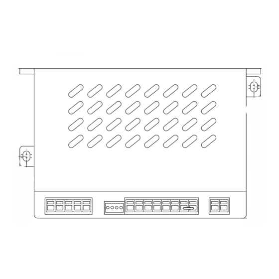
Dimensional Drawings and Layout
Device Dimensions and Component Layout
Mechanical dimensions and component layout of the protection devices.
Diagram Legend
Legend identifying components shown in the dimensional drawings.
Component Identification for Schematics (Part 1)
Thermostats, Fuses, and Control Units
Identification of thermostats, fuses, and control units (B1-B2, F1-F21).
Signal Lamps, Contactors, and Relays
Identification of signal lamps, contactors, and relays (H1-H8, K1-K9).
Time and Pulse Relays Identification
Identification of time and pulse relays (K3T, K4T, K5T, K7T).
Compressor, Inverter, Switch, Sensor Identification
Identification of compressor, inverter, switch, and sensor components (M1, N1, Q1, R1-R9).
Component Identification for Schematics (Part 2)
Switches and EMC Screening Units
Identification of switches (S1, S2, S4) and EMC screening units (U).
CSH Compressor Solenoid Valves
List of solenoid valves specific to CSH compressors (Y1-Y5).
HS.64/HS.74 Compressor Solenoid Valves
List of solenoid valves specific to HS.64/HS.74 compressors (Y1-Y3, Y6-Y8).
HS.85 Compressor Solenoid Valves
List of solenoid valves specific to HS.85 compressors (Y2-Y8).
Control and Protection Device Identification
Identification of the SE-B2 oil filter control and SE-C1/SE-C2 protection devices.
CSH Part Winding Start Wiring Diagram
Infinite Capacity Control
Infinite capacity control for CSH compressors.
Wiring Diagram Options
Options for ECO operation, liquid injection, and oil level monitoring.
CSH Part Winding Start: 4-Step Capacity Control
4-Step Capacity Control Details
4-step capacity control for CSH compressors.
Wiring Diagram Options
Options for ECO operation, liquid injection, and oil level monitoring.
CSH Star-Delta Start Wiring Diagram
Infinite Capacity Control
Infinite capacity control for CSH compressors.
Y/A Switching Time Relay Requirement
Time relay needed if Y/A switching time exceeds 2 s.
CSH Star-Delta Start: 4-Step Capacity Control
4-Step Capacity Control Details
4-step capacity control for CSH compressors.
Wiring Diagram Options
Options for ECO operation, liquid injection, and oil level monitoring.
HS.64/HS.74 Wiring Diagrams
Control Sequence Notes
Note on control sequences Y6/Y7 and manual SH-100.
ECO Operation Option (Path 21)
Option for ECO operation, specifying path 21.
Terminal Box Heating Element Option (Path 23)
Optional heating element for terminal box, specifying path 23.
HS.85 Part Winding Start Wiring Diagram
Infinite Capacity Control
Infinite capacity control for HS.85 compressors.
ECO Operation Option (Path 27)
Option for ECO operation, specifying path 27.
Terminal Box Heating Element Option (Path 28)
Optional heating element for terminal box, specifying path 28.
HS.85 Part Winding Start: 4-Step Capacity Control
4-Step Capacity Control Details
4-step capacity control for HS.85 compressors, dependent on conditions.
Operating Condition Limitation for CR50%
Limitation to minimum CR50% based on operating conditions.
Frequency Inverter Operation: SE-C1 and CSH
Legend Reference for Diagrams
References to legend pages for component identification.
K7T Delay vs. Inverter Ramp-Up Time
K7T delay time must match frequency inverter ramp-up time (max 5 s).
ECO and Liquid Injection Options
Options for ECO operation and liquid injection.
Frequency Inverter Operation: SE-C1 and HS.64/HS.74
Legend Reference for Diagrams
References to legend pages for component identification.
ECO Operation Option (Path 22)
Option for ECO operation, specifying path 22.
Terminal Box Heating Element Option (Path 24)
Optional heating element for terminal box, specifying path 24.
Frequency Inverter Operation: SE-C2 and HS.85
Legend Reference for Diagrams
References to legend pages for component identification.
ECO Operation Option (Path 28)
Option for ECO operation, specifying path 28.
Terminal Box Heating Element Option (Path 29)
Optional heating element for terminal box, specifying path 29.
Need help?
Do you have a question about the SE-C2 and is the answer not in the manual?
Questions and answers