Table of Contents
Advertisement
MANUAL
FOR ASSEMBLY AND OPERATION OF ELECTRIC FLOW-THROUGH BOILER WITH
RELAY CONTROL
PASSPORT
OF ELECTRIC BOILER WITH RELAY CONTROL ECOTERMAL
MR 6, 8, 10, 12, 15, 22, 30 kW MX 37, 45, 52, 60 KW
MODULE 6, 8, 10, 12, 15, 22, 30, 37, 45, 52, 60 KW
Bourgas 8000, 47 Slivnitsa Str
tel: 056/814 681; 056/814 215
E – mail: sales@ecotermal-bg.com
www.ecotermal-bg.com
- 1 -
Advertisement
Table of Contents

Related Manuals for Ecotermal 37 MX


Summary of Contents for Ecotermal 37 MX
- Page 1 FOR ASSEMBLY AND OPERATION OF ELECTRIC FLOW-THROUGH BOILER WITH RELAY CONTROL PASSPORT OF ELECTRIC BOILER WITH RELAY CONTROL ECOTERMAL MR 6, 8, 10, 12, 15, 22, 30 kW MX 37, 45, 52, 60 KW MODULE 6, 8, 10, 12, 15, 22, 30, 37, 45, 52, 60 KW Bourgas 8000, 47 Slivnitsa Str tel: 056/814 681;...
-
Page 2: Table Of Contents
Dear clients! „ECOTERMAL” Ltd. is thanking you for the good choice you made! Please get familiar in detail with the present manual in order to use the full scale of the advantages of the electric boilers with relay control that will secure for you comfortable, ecologic and economic heating through their quality, reliable and modern automation. -
Page 3: Recommendations
2. INTRODUCTION The flow-through electric boiler ECOTERMAL is a modern ecological source of heat designated for story and central heating of small and average size houses and production facilities. The main advantages of heating with electric power are mostly cost effectiveness, high efficiency, environmental friendliness and compactness. -
Page 4: Technical Description Of The Boiler
3. TECHNICAL DESCRIPTION OF THE BOILER Structure of the electric boiler/ module, see Fig. 3 page 7, Fig. 4 page 8, Fig. 5 page 9, Fig. 6 page 10. Equipment of the boilers’ models is shown in Tab. 6 page 15. Technical data and technical characteristics of the electric boiler/module, see Tab. -
Page 5: Connection To The Electric Network
6. CONNECTING TO THE ELECTRIC NETWORK - Connecting the electric switchboard to the power supply network and the boiler electric installation assembly should be carried out only by an expert with the necessary qualification. The power supply is connected through not severable joint according to the connection diagram. -
Page 6: Method Of Connecting The System To A Solid Fuel Boiler, Fig
Мethod of connecting of story (local) heating 1. Air bleeder 7. Safety valve 2. Electric heater 8. Shut off valve 3. Electric boiler 9. Manifold Box 4. Expansion tank 5. Circulation pump 6. Water filter Fig. 1 Method of connecting the system to a solid fuel boiler 1. - Page 7 ELECTRICAL BOILER MR 6 ÷ 30 kW Fig. 3 1. Frame 10. Heaters 2. Safety Valve by pressure 2.5 bar 11. Circulation Pump 4. Automatic breaker 12. Control Panel with additional protection 13. Pressure-gauge Valve 5. Emergency (blocking) thermostat 14. Expansion Tank 6.
- Page 8 ELECTRICAL BOILER MX 37 ÷ 60 kW Fig. 4 1. Frame 10. Heaters 2. Safety Valve by pressure 2.5 bar 11. Circulation Pump 4. Automatic breaker 12. Control Panel with additional protection 13. Pressure-gauge Valve 5. Emergency (blocking) thermostat 14. Power Wires 6.
- Page 9 ELECTRICAL MODULE K 6 ÷ 30 kW Fig. 5 1. Frame 9. Pressure-gauge 2. Safety Valve by pressure 2.5 bar 10. Heaters 4. Automatic breaker 12. Control Panel with additional protection 13. Pressure-gauge Valve 5. Emergency (blocking) thermostat 15. Thermostat Pocket 6.
- Page 10 MODULE K 37 ÷ 60 kW Fig. 6 1. Frame 9. Pressure-gauge 2. Safety Valve by pressure 2.5 bar 10. Heaters 4. Automatic breaker 12. Control Panel with additional protection 13. Pressure-gauge Valve 5. Emergency (blocking) thermostat 14. Power Wires 6.
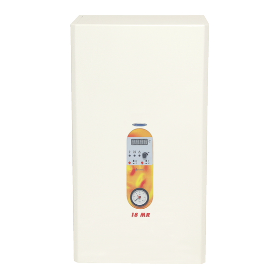
- Page 11 CONTROL PANEL 6 ÷ 60 kW Fig.7 1. Digital Display 2. Green LED Indication– Second Stage ON 3. Green LED Indication– First Stage ON 4. Button - First Stage OFF (when it is pressed) 5. Pressure-gauge 6. LED Indication of activated emergency thermostat 7.
- Page 12 SYSTEM CONTROL 6 ÷ 60 kW Fig. 8 To power wire X6 is getting operational power 240V/50Hz. It is secured by built-in breaker FS - 2A. X2 is connected to the management of the relays. X4 is connected to the block (emergency) thermostat.
- Page 13 Boiler/Module 6÷ ÷ ÷ ÷ 30 kW Fig. 9 Boiler/Module 37÷ ÷ ÷ ÷ 60 kW Fig. 10 - 13 -...
- Page 14 Dimensions of electric boilers/modules with relay control МR 6 - 30 6 - 30 height length width Module К 6 – 30 6 - 30 height length width MX / Module 37 - 60 37 - 60 height length width Tab.
-
Page 15: Equipment Of The Boilers' Models, Tab
Weight of the electrical boiler/module models Electrical boilers Electrical modules Power, Weight, Power, Weight, Model Model 6 MR 6 К 8 MR 8 К 31,0 22,0 10 MR 10 К 12 MR 12 К 15 MR 31,5 15 К 22,5...
Need help?
Do you have a question about the 37 MX and is the answer not in the manual?
Questions and answers