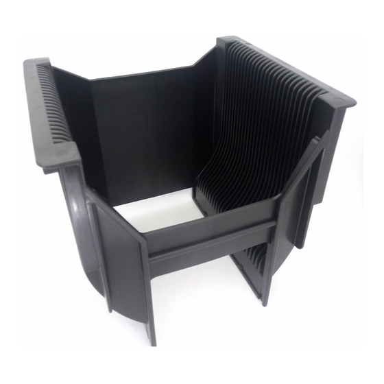
Summary of Contents for entegris PA192-80M Series
- Page 1 CRITICAL MATERIALS HANDLING 200 MM WAFER CARRIER INTERFACE MANUAL Installation and use manual Datum A...
-
Page 2: Table Of Contents
Product Warranties ......14 Contact Area C ........8 Overview At Entegris, we are committed to working with you, the equipment supplier, to provide simple solutions for our joint customers in the semiconductor industry. Our experience has shown that semiconduc-... -
Page 3: General Terminology And Definitions
Distance from Datum A to the front of the “H” bar web Inside width of the bottom track Overall width of the “H” bar at the top of the wafer carrier Overall width of the robotic pick-up flanges Section B-B Section E-E INSTALLATION AND USE MANUAL ENTEGRIS, INC. -
Page 4: Definitions
The right side of the carrier when viewed from the “H” bar end while positioned on its track. Track clearance The unobstructed area between the two carrier sides on the bar end. Wafer transfer The act of relocating wafers from one carrier into another. ENTEGRIS, INC. INSTALLATION AND USE MANUAL... -
Page 5: Wafer Plane
To reduce these problems, tolerance. Entegris continually strives to improve wafer Pocket center The imaginary plane that exactly plane dimensions. plane bisects each pocket. -
Page 6: Specification Description
Z = Bottom limit of the wafer plane zone for pocket N X = Pocket center plane distance for pocket N NOTE: The offset value is given as a negative value. Please use the absolute, or non-negative, value in the above calculations. ENTEGRIS, INC. INSTALLATION AND USE MANUAL... -
Page 7: Four Point Contact
• A192-80M-0215 • A198-80M-47C02 • A198-80MB-47C02 The Entegris wafer carriers listed below have a four point contact feature on the track only. They do not have a four point contact on the “H” bar end. They should be supported along the length of the two “H”... -
Page 8: General Interface Information
Information Wafers Horizontal Recommended Contact Points General Recommendations Entegris strongly urges the use of only recom- Entegris strongly recommends that only the contact mended contact points in developing wafer points detailed in this section be used to locate carrier interfaces. These are typically tightly wafer carriers for horizontal wafer handling. -
Page 9: Contact Area A
Ensure the wafer carrier is supported only on the four points of the “H” bar contact to ensure proper height to pocket (D1). Please see page 7 for more information. 12.7 mm (0.50”) maximum INSTALLATION AND USE MANUAL ENTEGRIS, INC. -
Page 10: Interface Points: Wafers Vertical
Sample Interface Plate Datum B This sample interface plate locates the wafer carrier with the wafers vertical by using Entegris Detail B recommended interface points. Use of the center notches provides the most accurate wafer carrier “H-bar”... -
Page 11: Contact Areas B And C
Endwall Flange Controlled Dimension features, it is important to reference the specifi- cations for the specific wafer carrier as features vary in design and location. If additional informa- tion is required, contact Entegris Applications Engineering. INSTALLATION AND USE MANUAL ENTEGRIS, INC. -
Page 12: H" Bar End Flanges
Top flanges run along the top length of the wafer carrier, parallel to the track. Endwall Handle Use of the top flanges for robotic movement and placement of the wafer carrier is acceptable only when precise placement is not required. Top Flanges ENTEGRIS, INC. INSTALLATION AND USE MANUAL... -
Page 13: Material Information
Very good Very low Good material for reliable interface. STAT-PRO 100 Poor Very good Very low Poor material for interface, still widely used. Blue Poor None Very low Very poor material for polypropylene interface. INSTALLATION AND USE MANUAL ENTEGRIS, INC. -
Page 14: Process Wafer Carriers
Flammability STAT-PRO 9000 0.04% STAT-PRO 9000 STAT-PRO 3000 0.05% STAT-PRO 3000 EMSTAT AR+ 0.01% EMSTAT AR+ STAT-PRO 100 0.02% STAT-PRO 100 Blue polypropylene 0.02% Blue polypropylene UL94 Natural PFA < 0.03% Natural PFA UL94 ENTEGRIS, INC. INSTALLATION AND USE MANUAL... -
Page 15: For More Information
For More Information Please call your Regional Customer Service Center today to learn what Entegris can do for you. Visit www.entegris.com and select the Customer Service link for the center nearest you. Terms and Conditions of Sale All purchases are subject to Entegris’ Terms and Conditions of Sale.


Need help?
Do you have a question about the PA192-80M Series and is the answer not in the manual?
Questions and answers