
Related Manuals for Honeywell Morley-IAS ZX1Se


Summarization of Contents
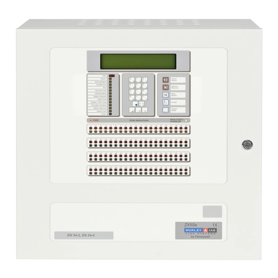
Introduction to ZX Fire Alarm Control Panels
Notice and Disclaimers
General disclaimer about manual accuracy and manufacturer's right to modify.
Warnings and Cautions for Safe Operation
Procedures to avoid injury and equipment damage, assuming user training.
National Approvals and Regulatory Compliance
Equipment must comply with national, regional, and local regulations.
EN54 Compliance Information
Details panel compliance with EN54-2/4 standards and optional functions.
User Control Levels and Passwords
User Control Level Definitions
Defines three user access levels and their capabilities.
Managing User Passwords
Information on programming and assigning User Level 2 passwords.
Level 3 Password Access
Specifies the default Level 3 password for installer access.
Panel Controls and Display Functions
Control Panel Key Operations
Describes the system control and interactive keys on the panel.
Front Panel LED Indicator Guide
Explains the meaning of LED indicators for panel and zone status.
Alphanumeric Display Information
Details the alphanumeric display and shows examples of fire/fault conditions.
Memory Lock for Configuration Security
Explains how to unlock system memory for configuration changes.
Enabling User Access Levels
Steps to enable Level 2/3 access by entering passwords.
Commissioning Menu Navigation
Overview of the three-screen structure of the commissioning menus.
Commissioning a New Fire Alarm System
Step 1: General System Setup
Clearing panel memory and inspecting factory default settings.
Step 2: Configure Signalling Loops
Steps for auto-learning, device assignment, and zone configuration.
Step 3: Configure Peripherals
Steps for configuring peripheral devices on the RS485 bus.
Step 4: Configure Sounder and Relay Outputs
Programming sounder ringing patterns and relay output operations.
Step 5: Configure Day Mode Operation
Setting up delayed, sensitivity, or verification modes.
Step 6: Configure Network Options
Setting up network addresses and parameters for networked systems.
Step 7: Commence Normal Operation
Final steps including password setup and memory locking.
Configure Panel Options
Accessing and Using the Configure Option
Navigating to and selecting the configure option for programming.
Configuring Signalling Loops
Details on auto-learning, calibrating, and managing devices on loops.
Auto Learn Functionality
Facility to automatically detect and identify loop devices.
Calibrating Detectors and Devices
Performing calibration and contamination checks on detectors.
Zone Assignment and Description
Assigning devices to zones and defining zone descriptions.
Viewing and Modifying Device Information
Displaying detailed device info and changing parameters like location text.
Setting Device Events and Alarm Thresholds
Configuring device events and adjustable pre-alarm/alarm levels.
Configuring Device Actions
Defining the specific action a device takes upon an event.
Group Assignment and Disablements
Managing group disablement of detectors using input devices.
Apollo Ancillary Sounder Configuration
Configuring Apollo ancillary sounders attached to devices.
Ancillary LED Configuration
Configuring ancillary LEDs for Morley-IAS and System Sensor protocols.
Peripheral Device Configuration
Peripheral Bus Device Management
Overview of driving input/output devices on the RS485 peripheral bus.
Peripheral Auto Learn Function
Automatically detecting peripheral devices connected to the bus.
Peripheral Device Calibration
Calibration procedures for peripheral devices.
Peripheral Device Zone Assignment
Assigning peripheral devices to specific zones.
Viewing Peripheral Device Details
Displaying information about peripheral devices fitted on the bus.
Configuring 8-Way Input Units
Setting actions for inputs on 8-way input boards.
Remote Control via Peripheral Cards
Using peripheral cards for remote control of panel functions.
Sounder Configuration and Operation
Sounder Output Connection Types
Describes the three methods of connecting sounders to the system.
Allocating and Programming Sounders
Programming ringing patterns and sounder operation relative to zones.
Sounder Pattern Configuration
Details various sounder patterns like OFF, DELAY, PULSE, DOUBLE KNOCK.
Advanced Sounder Patterns
Configuring OFF-PULSE-ON and OFF-ON-ON sounder patterns.
Addressable Sounder Circuit Controller Units (SCC)
Configuring SCC units for sounding fires in any zone.
Peripheral Loop Addressable Sounder Units
Programming sounders connected via peripheral loop cards.
Overriding Sounder Delays at Level 1
Facility to override any delayed sounder circuits at access Level 1.
Sounder Fault Monitoring
Detection and logging of open or short circuits on sounder inputs.
Relay and Control Key Functions
Relay Output Operations
Programming and functions of relay outputs, noting exceptions.
Fault Relay Configuration
Configuration of fault output relay 1 for failsafe operation.
Control Key Disable Option
Using a keyswitch to disable panel control keys for security.
PC Remote Programming Capabilities
Controlling the panel via PC for uploading/downloading configuration data.
Inspection and System Time/Date
Inspect Option for Data Review
Viewing commissioning data without risk of inadvertent changes.
Time and Date Setting Options
Checking and modifying the panel's date and time functions.
System Memory Clear Function
Clearing system configuration memory to factory default settings.
Crystal Frequency Adjustment
Entering measured crystal frequency for accurate date/time clock.
Program Integrity and Power
Program Integrity Check
Displaying the status of system memory (ROM and RAM checksums).
PC Programming with FIRE Software
Using PC software to program and manage panel configurations.
Power Supplies Status Monitoring
Displaying the current state of AC Mains and Battery supplies.
Password Management Options
Defining the number and values of User Level 2 passwords.
Day Mode and Operational Modes
Day Mode Configuration Overview
Setting up operating modes based on time of day.
Configuring Day Modes
Selecting between delayed, sensitivity, and verification modes.
Delayed Mode Operation
Configuring the panel to operate in a delayed alarm mode.
Sensitivity Mode Settings
Adjusting detector sensitivity for pre-alarm and alarm signals.
Verification Mode for False Alarm Reduction
Using a delay to reduce false alarms from smoke detectors.
System Setup and Event Logging
Panel Setup Options Configuration
Configuring panel settings like language, loop drivers, and approvals.
Event Log for Diagnostics
Using diagnostic mode to pinpoint loop wiring and detector problems.
Network Configuration and Protocols
Network System Configuration
Configuring panel operation on a networked system.
Panel Network Address Setup
Setting up network addresses for panels in a shared zone system.
Port B Protocol Settings
Defining serial interface settings for various PC and pager protocols.
System Events and Normal Operation
System Events for Advanced Programming
Flexible programming for cause-and-effect using system events.
System Event Modes and Logic
Accessing general events, logic sequences, and output definitions.
Defining Event Outputs
Assigning system events to output devices like relays or sounders.
Returning Panel to Normal Operation
Placing the panel into its normal operating state after commissioning.
Supplementary Information and Features
Locating Earth Faults in Wiring
Procedure for identifying and locating earth faults in external wiring.
Overriding Delays on Individual Outputs
Methods to override any delayed circuits at access Level 1.
Optional System Features
Details optional features like output control and coincidence detection.
Disablement of Addressable Points
Facility to disable/enable addressable points at User Level 2.
Test Condition for Detector Operations
Using User Level 2 to test fire alarm detector operations.
Network Disablement/Enablement Management
Managing network disablement/enablement from the Master panel.
Printer Setup Configuration
Configuring the panel for different types of connected printers.
Hochiki Multi-Sensor Device Support
Details on support for Hochiki Multi-Sensors from software version 824.
System Sensor/M-IAS Device Diagnostics
Understanding analogue values for System Sensor/M-IAS devices.
System Sensor/M-IAS Detector Modes
Modes of operation and sensitivity for multi-sensor/laser detectors.
Need help?
Do you have a question about the Morley-IAS ZX1Se and is the answer not in the manual?
Questions and answers