
Related Manuals for Hardi ZENIT 600


Summarization of Contents
EC Declaration
EC Declaration of Conformity
Statement of compliance with machinery and EMC directives.
Safety
Operator safety
Guidelines for safe operation and hazard awareness.
Symbols
Explanation of safety symbols used throughout the manual.
Precautions
Important safety notes and operating practices before use.
Description
General information
Introduction to the machine's components and overall structure.
Overview
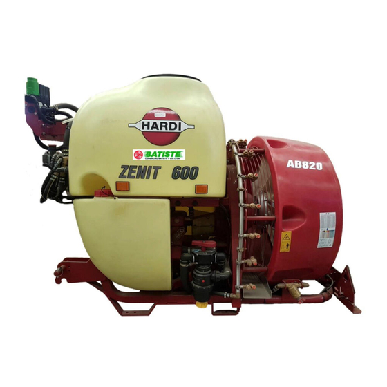
Labeled diagram showing key parts of the sprayer unit.
Use of the mistblower
Proper application and intended use of the HARDI mistblower.
Roadworthiness
Requirements for safe operation on public roads and compliance with regulations.
Identification plate
Location and information provided on the machine's identification plate.
Chassis
Description of the robust and durable metal chassis construction.
Tank
Details on the main tank material, capacity, and level indicators.
Liquid system
General information
Overview of the suction and pressure circuits, including HLC.
The liquid circuit
Description of the manifold system for distributing liquid to various components.
Diaphragm pump
Information on diaphragm pump models, pressure limits, and characteristics.
Valves
Location and function of suction valves for selecting liquid sources.
Valves and symbols
Identification of valves by colored discs and associated symbols for optional accessories.
Manifold system
Details on the pressure circuit distributor with mechanical valves for different functions.
Safety valves
Function of safety valves to protect the liquid circuit from overpressure.
Blue valve – Blue disc = Return valve
Explanation of the return manifold valve's function in directing excess flow.
Pressure pulsation damper
Role of pulsation dampers in stabilizing pump flow and pressure.
Circuit Diagram
Schematic illustrating the Zenit 400-600-1000-EVC/2 liquid circuit.
Suction filter
Location and function of the suction filter within the liquid circuit.
Safety valve
Description of the cast iron safety valve and its manifold connections.
Pressure manifold
Details on the plastic pressure manifold and its functions.
Suction and pressure pulsation dampers
Explanation of dampers for stabilizing pump flow.
Agitator
Description of the ventury-shaped agitators within the tank.
Operating unit
Overview of different types of operating units available for the sprayer.
Filters
Location and maintenance recommendations for pressure filters.
Powder mixer
Function of the powder mixer for rinsing and dissolving powder chemicals.
TurboFiller
Chemical inductor, TurboFiller (optional)
Safe and convenient filling of chemicals using the TurboFiller.
TurboFiller suction valve
Operation of the suction valve for the TurboFiller.
TurboDeflector valve
Activating the Vortex flushing of the TurboFiller.
Chemical Container Rinsing lever
Using the lever for rinsing empty containers and the hopper.
Axial blower units
Technical information
Details on the design and features of axial blower units.
Air flow for axial air kits
Table detailing air flow specifications for various axial air kit models.
Protective grid
Importance and function of protective grids for safety and preventing foreign bodies.
Deflectors
How deflectors increase spray efficacy by reducing drift and directing air.
Gearbox
Description of the 2-speed gearbox with neutral position for AG820 and AG920.
Fan
Information on the axial fan's blades and their angle adjustability.
Adjusting the fan AB820
Step-by-step guide to adjusting fan blade angles for optimal air flow.
Centrifugal Blower Units
General information
Overview of the blower unit's location, components, and turbine models.
Components
Labeled diagram of the centrifugal blower unit components.
Air flow of HF540, HF540D and HF640D centrifugal turbines
Table detailing air flow specifications for centrifugal turbine models.
Protective grid
Importance of protective grids for safety and preventing foreign bodies.
Gearbox
Details on the two-speed gearbox with neutral position for HF blowers.
HF540, HF540D and HF 640D Turbine
Information on galvanized steel turbines used in HF blower units.
Clutch (All blower types)
Function of the integrated clutch for smooth start-up and stop of the fan.
Booms
Light kit
Installation and use of the tractor lighting kit for road safety.
The LINER boom
Description of the LINER boom's manual and START FIX adjustment systems.
The ATLAS boom
Overview of ATLAS boom versions: START, AGILE, SOLID, and GV.
The BOXER boom
Description of BOXER boom additions: START, AGILE, and SOLID structures.
The CRONOS boom
Versions of CRONOS booms: SOLID, RIDER, VARIA, and GV, with tilt options.
Variant boom
Details on the hydraulically folded Variant boom, including folding types.
Break away clutch
Adjustment of break away clutches for boom wings based on weight and conditions.
Pneumatic spray system
Low-pressure system using air speed to create fine mist and turbulence.
Hydropneumatic spray system
Medium-high pressure system for even liquid distribution via high turbulence.
IRIS system, continuation of Hydro pneumatic system
IRIS system for individual air adjustment and precise droplet control.
Starting up
General information
Initial steps and precautions before operating the equipment.
Unloading the mistblower from the truck
Safe procedures for unloading the mistblower using lifting equipment.
Before starting up for the first time
Recommended anti-corrosion treatment for metal parts before initial use.
Counterweights
Checking the need for counterweights on the tractor for stability.
Coupling the driveshaft
Step-by-step guide for connecting and adjusting the driveshaft.
Hooking up the mistblower
Procedure for attaching the mistblower to the tractor's hydraulic lift arms.
Hydraulic connections
General information
Precautions for connecting hydraulic couplings and checking oil levels.
Tractor requirements
Specifications for tractor hydraulic pressure, flow, and outlet types.
Electrical connections
General information
Important notes on voltage, polarity, and connectors for electrical components.
Electrical operating units
Guidance on selecting and mounting control boxes in the tractor cab.
Rate controller
Rate controller DB 3610
Introduction to the DB 3610 rate controller, its display, and connected boxes.
Rate controller DB 3620
Details on the DB 3620 rate controller, its display, and connected boxes.
Fluid circuit
Suction filter
Instructions for cleaning the suction filter and its components.
Pressure damper
Adjusting pressure damper air pressure based on spraying pressure.
Diaphragm pump
Ensuring the diaphragm pump is properly greased before use.
Deflectors
V deflector
Adjusting the V deflector for optimal spray targeting in orchards.
Top S or L
Adjusting Top S and Top L deflectors for air outlet direction.
Adjustable bottom deflector
Using the adjustable bottom deflector to avoid ground turbulence.
DUO P deflector
Fixed position deflector with accessible nozzle holders for calibration.
DUO T and V deflector
Adjusting DUO T and V deflectors for direction of air and spray mist.
JET deflector
Adjusting both top and bottom parts of the JET deflector for target alignment.
Booms
General information
Overview of boom options for adapting to various crops.
FIX
Description of the FIX boom's height and width adjustment features.
START
Details on the START boom's telescopic width adjustment and bracket options.
ATLAS START
Adjustment of outer spray devices and center sections for ATLAS START booms.
ATLAS AGILE
Description of ATLAS AGILE booms combining width adjustment with FIX bracket.
ATLAS SOLID FIX and ATLAS SOLID FIX GV
Specifications for ATLAS SOLID FIX booms and their GV variants.
ATLAS SOLID CONVERT and ATLAS SOLID GV CONVERT
Adjustment details for ATLAS SOLID CONVERT and GV CONVERT boom parts.
BOXER START
Telescoping adjustment for BOXER START booms and center section.
BOXER SOLID VERTICAL FIX or CONVERT
Telescope range for BOXER SOLID VERTICAL booms and side adjustment.
BOXER SOLID HORIZONTAL
Telescoping range for BOXER SOLID HORIZONTAL booms and side adjustment.
Adjustment of BOXER boom
Procedure for adjusting telescoping slack in BOXER booms.
CRONOS BOOM
Overview of CRONOS boom versions: SOLID, RIDER, GV, VARIA.
RIDER
Features of RIDER booms including suspension and maintenance.
VARIA
Hydraulic side adjustment and telescoping mechanism of VARIA booms.
CRONOS GV
CRONOS GV booms with RIDER features and individual wing tilt.
General for all boom models
Common adjustments and features applicable to all boom models.
Break away clutch
Adjustment of break away clutches for boom wings based on weight and conditions.
Adjustment of hydraulic fold
Adjusting the folding cylinder for correct boom folding positions.
Transport bracket
Securing the boom wing in transport using the transport bracket.
Adjustment of upright
Adjusting the upright for slack between tubes and maintaining nylon friction parts.
Adjustment of out spray device
Manual adjustment of the out spray device position.
The hydraulic version
Hydraulic adjustment of outer positioning for spray devices.
Adjustment of inner 4 spray device
Positioning of the inner spray device using optional S brackets.
Hydraulic adjustment of the Convert brackets
Hydraulic side adjustment of Convert brackets from the tractor cabin.
IRIS system setup
Setup and adjustment of the IRIS system for precise spray control.
Cannons
Calibration
Instructions for downloading calibration software and checking speed.
Operation
Blower unit
Safety information and gear selection for the blower unit.
Safety information
Critical safety warnings regarding fan operation and road use.
Selecting the gear
How to select gears (low, high, neutral) for the blower unit.
While moving the Sprayer
Procedures for safely moving the sprayer with unfolded or bracketed booms.
Adjusting the fan AB820
Step-by-step guide to adjusting fan blade angles for optimal air flow.
Single side blinds (Optional)
Using side blinds to prevent spray drift towards sensitive areas.
Liquid and air circuits
Filling/washing location requirements
Guidelines for selecting safe locations for filling and washing the sprayer.
Suction Filter
Instructions for cleaning the suction filter and its components.
Filling/washing location requirements
Further guidelines on safe filling and washing locations, including legal compliance.
Filling with water
Procedure for filling the main tank with water before adding chemicals.
Draining the main tank
Steps for emptying the main tank using the drain valve.
Pressure filters
Importance and maintenance of pressure filters to prevent nozzle clogging.
Agitation
How the dual-nozzle agitation system ensures uniform liquid mixing.
Clean water tank
Use and filling of the clean water tank for washing and cleaning.
Powder mixer
Operation of the powder mixer for dissolving powder chemicals.
Filling through tank lid
Method for filling the main tank using the top lid and filter.
Filling the rinsing tank
Capacity and procedure for filling the integrated rinsing tank.
Rinsing nozzle
Function of the rotating rinsing nozzle inside the main tank.
Unexpected interruptions
Procedure for cleaning the system during unexpected stops.
Filling the clean water tank
Location and purpose of the clean water tank.
Drain valve
Accessing and operating the drain valve for safe emptying.
Manifold system
Operation of the manifold system with three mechanical valves.
Filling liquid chemicals by HARDI TurboFiller (optional)
Step-by-step guide for filling chemicals using the TurboFiller.
TurboFiller rinsing
Two methods for rinsing the TurboFiller and chemical containers.
Power supply
Power supply
Requirements and considerations for the 12V DC power supply.
Installation of control unit brackets
Guidance on mounting control unit brackets in the tractor cab.
Operating Units
SB 3002 or SB 3004
Control box for SV operating units with section valves and pressure regulation.
SV operating unit
Manual pressure regulation and section valve operation for SV units.
SB 3012 or SB 3014 etc.
Control boxes for motorized operating units like CB2 and CB4.
CA operating unit
Operation of CA units via tractor cabin switch box for section and pressure control.
SB 3012 or SB 3014 etc.
Control boxes for motorized operating units, maintaining constant pressure.
FB 3610
Functionality of the FB 3610 control box for valves and hydraulics.
CB operating unit
Pressure equalization and regulation for CB operating units.
CB operating unit with by pass valve
Use of bypass valve for low dose rates in pneumatic sprayers.
Hydraulic control boxes
Control boxes for hydraulic functions, including HB models.
HB 3610
Functions of the HB 3610 hydraulic control unit.
The Joystick S selector
Installation and operation of the Joystick S selector for hydraulic functions.
Cannon L-M-T
Hydraulic engine and spout lifting cylinder requirements for CANNON models.
Hydraulic control of the CANNON
Control of lifting cylinder and spout rotation for CANNON models.
The hydraulic adjustment
Adjusting oil flow using Allen bolts for boom movement speed.
HC 3100 control box
HC 3100 control box features, including vegetation sensor connection.
Vegetation sensor is optionally equipped
Automatic operation of the sprayer based on tree or bush detection.
Rate controller DB3610 and DB3620
Detailed layout and function of the DB3610/DB3620 rate controller display.
Example of speed and pressure limit settings
Setting pressure and speed limits to optimize spray application.
Adjusting the BK/2 Operating Unit
Procedure for adjusting constant pressure valves in BK/2 operating units.
MC/2 operating unit
High-pressure manual operating unit with pressure valve and remote levers.
Cleaning
General information
Importance of a maintenance program including comprehensive cleaning procedures.
Steps to follow
General steps for cleaning the mistblower, including chemical handling and disposal.
Cleaning and maintaining the filters
Ensuring filter efficiency and preventing blockages through regular cleaning.
Liquid and air circuits
Filling/washing location requirements
Guidelines for selecting safe locations for filling and washing the sprayer.
Suction Filter
Instructions for cleaning the suction filter and its components.
Nozzles
Nozzles
Cleaning, replacing, and checking nozzles for optimal spray patterns.
Cleaning the tank and liquid system
Detailed procedure for cleaning the tank, system components, and filters.
Use of rinsing tank and rinsing nozzles (optional)
Use of rinsing tank and rinsing nozzles (optional)
Using the rinsing tank for diluting residues and cleaning the system.
In-field diluting before cleaning
Diluting spray liquid residue in the field before cleaning the sprayer.
Rinsing the tank and liquid system
Step-by-step guide for rinsing the tank and liquid system components.
Cleaning of Main tank
Procedure for thorough cleaning of the main tank, including using detergents.
Rinsing when main tank is not empty
Process for rinsing the system when the main tank is not fully empty.
Maintenance
Lubrication
General information on storing lubricants and cleaning lubrication points.
General information
Guidelines for storing lubricants and cleaning points before application.
Recommended lubricants
Table listing recommended lubricants for various components.
Lubricating and greasing the mistblower
Diagram showing lubrication points on the mistblower.
Service and maintenance intervals
Recommended intervals for maintenance tasks based on working hours.
General information
Factors influencing maintenance intervals and seeking dealer assistance.
Every 10 working hours – Spray circuit
Tasks for the spray circuit every 10 working hours, including leak checks.
Every 50 working hours – Transmission shaft, chassis, air pressure and diaphragm pump
Maintenance for transmission, chassis, air pressure, and pump every 50 hours.
Every 100 working hours – Drawbar
Greasing and checking the drawbar and moveable parts every 100 hours.
Every 250 working hours – Wheels, brakes, hoses and gearbox
Checks for wheels, brakes, hoses, and gearbox every 250 hours.
Every 1000 working hours – Full service
Comprehensive service including oil changes and clutch inspection every 1000 hours.
Regular maintenance
Routine maintenance tasks performed at regular intervals.
Every 10 working hours – Suction filter
Servicing the suction filter, including O-ring replacement.
Every 10 hours of operation – Pressure filters
Inspecting and cleaning pressure filters, and checking gearbox oil level.
Every 10 working hours – Nozzles
Cleaning, replacing, and checking nozzles for optimal spray patterns.
Every 1000 working hours - Gearbox oil change
Procedure for changing gearbox oil after initial hours and annually.
Every 1000 working hours - Fan clutch inspection
Dismantling, inspecting, cleaning, and lubricating the fan clutch.
Every 1000 working hours - Fan transmission shaft inspection
Cleaning, inspecting, and lubricating the fan transmission shaft.
Occasional maintenance
Maintenance tasks performed as needed, rather than on a fixed schedule.
Replacing the 321 valves and diaphragms
Procedure for replacing valves and diaphragms in the 321 pump.
SV operating unit
Operation of SV unit pilot lines and cleaning of components.
CB Section valve
Maintenance of CB operating motor valve, including micro switch replacement.
Sealing in the operating unit.
Replacing wear and tear parts in the valve's on/off function.
Cleaning the air kit
Preventing unbalance by cleaning dust and dirt from the air kit.
Tank level indicator adjustment
Checking and adjusting the tank level indicator cord length.
Replacing the valves and 363 and 463 diaphragms
Repair kits and procedures for replacing valves and diaphragms in 363/463 pumps.
Lubrication
General information
Guidelines for storing lubricants and cleaning lubrication points.
Recommended lubricants
Table listing recommended lubricants for various components.
Grease Gun Calibration
Grease Gun Calibration
Calibrating the grease gun to ensure correct grease application.
Greasing the Pump
Procedures for factory greasing, normal operation, and post-disassembly greasing.
Service and Maintenance Intervals
Service and Maintenance Intervals
Recommended intervals for pump greasing.
50 Hours Service - Greasing the Pump
Specific instructions for greasing the pump every 50 hours.
Occasional Maintenance
Lifting and Removing the Pump
Safe procedures for lifting and removing the pump using appropriate gear.
Pump Valves and Diaphragms Renewal
Steps for removing plastic covers and accessing pump valves/diaphragms.
Valves
Loosening head bolts, removing heads, and changing valves correctly.
Diaphragms
Replacing diaphragms, checking drain holes, and reassembling with torque settings.
Adjusting the 3-way valve
Adjusting the 3-way valve for proper handle operation and cleaning mating faces.
Replacing the driveshaft protector guard
Procedure for removing, replacing, and re-greasing the driveshaft protector guard.
Replacing the driveshaft crossheads
Steps for removing and replacing driveshaft crosshead components.
Replacing the seal on the drain valve
Replacing the seal and seat on the drain valve.
Storing the mistblower at the end of the season
Off-season storage program to protect components from chemical residues and damage.
Preparing the machine for use after storage
Steps to prepare the machine for the new season after storage.
Troubleshooting
Operational problems
Common factors present in most breakdowns and initial checks.
General information
Identifying common causes of breakdowns and initial checks.
Fluid circuit
Troubleshooting table for issues related to the fluid circuit, such as no spray or pressure loss.
Blower unit
Troubleshooting table for excessive noise, vibrations, or noises in the blower unit and gearbox.
Electrical problems
Emergency function – Fluid circuit
Manual operation of CB units during power faults.
Technical specifications
Dimensions
Dimensional data for Zenit Axial and Zenit Liner models.
Zenit Axial
Table of dimensions and weight for Zenit Axial models.
Zenit Liner
Table of dimensions and weight for Zenit Liner models.
Conversion factors (SI to Imperial)
Factors for converting SI units to Imperial units used in the manual.
Pump model 363/7
Specifications and operational data for the 363/7 pump.
Pump model 321/10
Specifications and operational data for the 321/10 pump.
Specifications
Performance data tables for various pump and component specifications.
321/7 and 321/10 Diaphragm
Performance data for 321/7 and 321/10 diaphragm pumps at various speeds and pressures.
363/7 Diaphragm
Performance data for the 363/7 diaphragm pump at various speeds and pressures.
Filters and nozzles
Specifications for filter mesh widths and nozzle types.
Temperature and pressure range
Operational temperature range and safety valve pressure limits.
Materials and recycling
Information on materials used and disposal guidelines for the mistblower.
Disposing of the mistblower
Procedures for cleaning and disposing of the mistblower at the end of its working life.
Need help?
Do you have a question about the ZENIT 600 and is the answer not in the manual?
Questions and answers