Table of Contents
Advertisement
SERVICE MANUAL
Ver. 1.0 2009.02
• HCD-ZX66i/ZX99i are the tuner, iPod,
CD and amplifi er section in LBT-ZX66i/ZX99i.
AUDIO POWER SPECIFICATIONS
POWER OUTPUT AND TOTAL HARMONIC DISTORTION:
HCD-ZX99i:
With 6-ohm loads, both channels driven, from 120 Hz – 10 kHz; rates 200
watts per channel minimum RMS power, with no more than 0.7 % total
harmonic distortion from 250 miliwatts to rated output.
HCD-ZX66i US model:
With 6-ohm loads, per channel driven, from 120 Hz – 10 kHz; rates 220
watts per channel minimum RMS power, with no more than 0.7 % total
harmonic distortion from 250 miliwatts to rated output.
Amplifi er section
HCD-ZX99i:
The following are measured at
AC 120 V, 60 Hz
Front/Surround speaker
Power output (rated):
270 W + 270 W (at 6 Ω, 1 kHz, 10 % THD)
RMS output power (reference):
180 W × 2 + 180 W × 2 (6 Ω at 1 kHz, 10 % THD)
HCD-ZX66i
The following are measured at
AC 120 V, 60 Hz
Front speaker
Power output (rated):
280 W (at 6 Ω, 1 kHz, 10 % THD)
RMS output power (reference):
210 W × 2 (6 Ω at 1 kHz, 10 % THD)
Sony Corporation
9-889-432-01
2009B04-1
Audio&Video Business Group
©
2009.02
Published by Sony Techno Create Corporation
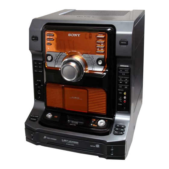
HCD-ZX66i/ZX99i
Photo: HCD-ZX99i
CD
Section
SPECIFICATIONS
COMPONENT Hi-Fi STEREO SYSTEM
Model Name Using Similar Mechanism
CD Mechanism Type
Base Unit Name
Optical Pick-up Name
Inputs
PHONO IN L/R:
Sensitivity 3 mV, impedance 47 kilohms
MIC 1/MIC 2:
Sensitivity 1 mV, impedance 10 kilohms
GAME INPUT AUDIO L/R:
Sensitivity 250 mV, impedance 47 kilohms
GAME INPUT VIDEO:
1 Vp-p, 75 Ω
PC IN L/R:
Sensitivity 250 mV, impedance 47 kilohms
Outputs
PHONES:
accepts headphones of 8 Ω or more
VIDEO OUT:
max. output level 1 Vp-p, load impedance 75 ohms
US Model
HCD-ZX66i/ZX99i
Canadian Model
HCD-ZX66i
HCD-ZX9
CDM79B-F1BD81
BU-F1BD81A
KSM-215DCP/C2NP
– Continued on next page –
Advertisement
Table of Contents

Related Manuals for Sony HCD-ZX99i


Summarization of Contents
System Specifications Overview
Disc Player and Tuner Details
Covers disc player specs (laser, freq response) and tuner specs (FM/AM ranges).
iPod and General Information
Details iPod power, general specs (power, dimensions, mass), and accessories.
Safety Warnings
Component Safety Criticality
Warns about components critical for safety and the need for SONY replacement parts.
Component Handling and Repair Notes
Chip Components and Circuit Boards
Notes on chip component replacement, flexible circuit board repair, and unleaded solder.
Optical Pick-up and Laser Safety
Precautions for handling optical pick-up and checking laser diode emission safely.
Safety Checks
AC Leakage Test Procedures
Describes methods and limits for checking AC leakage current on exposed metal parts.
Disc Playback Notes
Disc Type Compatibility
Notes on DualDisc compatibility and potential issues with copy-protected music discs.
SECTION 1 SERVICE NOTE
CD BU Block Service Position
Illustrates the service position for the CD BU block within the chassis.
SECTION 1 SERVICE NOTE
PANEL COM Board Service Position
Shows how to access and service the PANEL COM board by manipulating a gear.
SECTION 1 SERVICE NOTE
Power Amp and CD Changer Service Positions
Details service positions for the POWER AMP board and CD CHANGER mechanism.
SECTION 2 GENERAL
Unit Controls Overview
Identifies unit controls and buttons via front and top view diagrams.
SECTION 2 GENERAL
Remote Control Operation
Explains the functions of buttons on the RM-AMU008 remote control.
Getting Started
System Connections Guide
Explains how to connect speakers, antennas, and various input/output jacks for system setup.
Getting Started
Using the iPod
Instructions on how to connect and use an iPod with the system, including dock adapter.
Using the Remote
Details how to insert batteries and use the remote control, including battery life notes.
SECTION 3 DISASSEMBLY
Disassembly Flowchart
Outlines the step-by-step order for disassembling the set into major components.
SECTION 3 DISASSEMBLY
3-1. CASE Disassembly
Details the disassembly steps for the main case of the unit, including screws and claws.
3-2. LOADING PANEL Disassembly
Illustrates the process for disassembling the loading panel, including gear manipulation.
SECTION 3 DISASSEMBLY
3-3. FRONT PANEL SECTION Disassembly
Shows how to disassemble the front panel section, including wires and connectors.
3-4. GAME HP BOARD, MIC BOARD Disassembly
Details the disassembly of the GAME HP and MIC boards and related components.
SECTION 3 DISASSEMBLY
3-5. BACK PANEL SECTION Disassembly
Illustrates the steps for disassembling the back panel section, including cables and connectors.
3-6. BOARDS SECTION Disassembly
Shows the disassembly of various boards within the unit, including flat cables.
SECTION 3 DISASSEMBLY
3-7. CD MECHANISM SECTION Disassembly
Details the disassembly of the CD mechanism section, including screws and cables.
3-8. MAIN BOARD Disassembly
Shows the disassembly steps for the main board, including connectors and flat cables.
SECTION 3 DISASSEMBLY
3-9. TABLE ASSY Disassembly
Illustrates the disassembly of the table assembly, including trays and brackets.
3-10. SE-130 BOARD Disassembly
Details the disassembly steps for the SE-130 board, including connectors and flat cables.
SECTION 3 DISASSEMBLY
3-11. TD BELT Replacement
Shows how to disassemble components to access and replace the TD belt.
3-12. DC MOTOR (M901) Disassembly
Illustrates the disassembly and removal of the DC motor (M901) and its associated parts.
SECTION 3 DISASSEMBLY
3-13. OPTICAL PICK-UP Disassembly
Details the disassembly and handling of the optical pick-up, including springs and screws.
3-14. BD81A BOARD Disassembly
Shows the disassembly steps for the BD81A board, including solder points.
SECTION 4 TEST MODE
GC TEST MODE
Checks fluorescent tube, LEDs, keys, JOG, VOLUME, model, and software version.
MC TEST MODE
Checks operations of Amplifier and Tuner sections, including amplifier GEQ and volume response.
COLD RESET Procedure
Clears all data, including preset data, to initial conditions for customer release.
VACS ON/OFF Function
Switches the VACS (Variable Attenuation Control System) ON or OFF via button combination.
TUNER STEP CHANGE Function
Toggles the AM channel step interval between 9 kHz and 10 kHz via button combination.
CD SERVICE MODE Operation
Allows free movement of the CD sled motor for cleaning the optical pick-up.
SECTION 4 TEST MODE
CD AGING MODE Operation
Used for operation check of the CD section, repeating operations to test functionality.
CD ERROR CODE MODE Function
Displays CD error codes, total error counts, and details of mechanical/disc errors.
SECTION 4 TEST MODE
CD REPEAT 5 LIMIT OFF MODE
Enables CD repeat playback for limitless times instead of the default 5 repetitions.
CD SHIP MODE Operations
Moves optical pick-up for vibration durability and clears/preserves RAM data.
CD POWER MANAGE Function
Switches power supply to the BU ON/OFF during TUNER function to affect reception.
CD TRAY LOCK MODE
Locks the disc tray, preventing it from opening via buttons, indicated by "LOCKED".
VACS DISPLAY Mode
Checks the VACS level and APVACS level triggered by signal and abuse protection.
SECTION 5 ELECTRICAL ADJUSTMENTS
CD Section Adjustments
CD Section Adjustments
SECTION 5 ELECTRICAL ADJUSTMENTS
S-Curve Check
Confirms symmetrical S-curve waveform and peak-to-peak level for focus servo adjustment.
RF Level Check
Checks RF signal waveform clarity and RFAC signal level for RF amplifier adjustment.
SECTION 6 DIAGRAMS
Circuit Boards Location
Provides a diagram showing the location of various circuit boards within the unit.
Waveforms
Main Board Waveforms
Displays waveforms for IC401 (XC-OUT) and IC401 (X-OUT) on the Main board.
Panel Com Board Waveforms
Displays waveforms for IC901 (X OUT) on the Panel Com board.
IC Block Diagrams
IC251 BA5947FM-E2 (BD81A Board)
Block diagram and pin description for IC251 on the BD81A board.
IC301 TC94A34FG-002 (BD81A Board)
Block diagram and pin description for IC301 on the BD81A board.
IC501 BA00BC0WCP-V5E2 (MAIN Board)
Block diagram and pin description for IC501 on the main board.
IC514 BA6956AN (MAIN Board)
Block diagram and pin description for IC514 on the main board.
IC515 BA6956AN (MAIN Board)
Block diagram and pin description for IC515 on the main board.
IC Block Diagrams
IC101 R2A15216FP (MAIN Board)
Block diagram and pin description for IC101 on the main board.
IC Block Diagrams
IC102 R2S15207FP (MAIN Board)
Block diagram and pin description for IC102 on the main board.
IC903 NJM2760V-TE2 (PANEL COM Board)
Block diagram and pin description for IC903 on the Panel Com board.
IC Block Diagrams
IC701 STK412-240M-E (SURROUND Board)
Block diagram for IC701 on the Surround board (HCD-ZX99i).
IC601 STK412-240M-E (POWER AMP Board)
Block diagram for IC601 on the Power Amp board (HCD-ZX99i).
IC Block Diagrams
IC600 STK412-150C (POWER AMP Board)
Block diagram for IC600 on the Power Amp board (HCD-ZX66i).
IC627 RT8H015C-T112-1 (POWER AMP Board)
Block diagram and pin description for IC627 on the Power Amp board.
IC Pin Function Descriptions
BD81A BOARD IC101 CXD3059AR
Lists pin functions for IC101 on the BD81A board (RF AMP, DIGITAL SIGNAL PROCESSOR).
IC Pin Function Descriptions
MAIN BOARD IC401 R5F3640MDFAR
Lists pin functions for IC401 on the Main board (SYSTEM CONTROL).
IC Pin Function Descriptions
PANEL COM BOARD IC901 MB90M407PF-G-146E1
Lists pin functions for IC901 on the Panel Com board (DISPLAY DRIVER, KEY CONTROL).
SECTION 7 EXPLODED VIEWS
7-1. BACK PANEL SECTION
Shows an exploded view of the back panel section and its parts.
SECTION 7 EXPLODED VIEWS
7-2. FRONT PANEL SECTION (1)
Provides an exploded view of the front panel section (part 1), showing components and their part numbers.
SECTION 7 EXPLODED VIEWS
7-3. FRONT PANEL SECTION (2)
Provides an exploded view of the front panel section (part 2), showing knobs and boards.
SECTION 7 EXPLODED VIEWS
7-4. CHASSIS SECTION
Shows an exploded view of the chassis section and its components, including transformers and fuses.
Need help?
Do you have a question about the HCD-ZX99i and is the answer not in the manual?
Questions and answers