
Related Manuals for Mec 3772ES


Summarization of Contents
INTRODUCTION
GENERAL SAFETY TIPS
Provides essential safety guidelines and warnings for operating and maintaining the MEC aerial work platform.
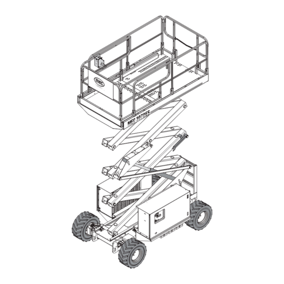
PRIMARY MACHINE COMPONENTS
Identifies and illustrates the main components of the MEC aerial work platform.
PRIMARY MACHINE COMPONENTS: COMPARTMENTS
Details the components located within the control and power modules of the machine.
PRIMARY MACHINE COMPONENTS LOCATOR
Maps major components to their respective sections in the manual for easy reference.
SPECIFICATIONS: ANSI MODELS
Lists technical specifications for ANSI compliant models of the aerial work platform.
SPECIFICATIONS: CE MODELS
Lists technical specifications for CE compliant models of the aerial work platform.
LUBRICATION
Provides a chart detailing lubrication points, specifications, and recommended frequencies.
SECTION 1 HYDRAULICS
Hydraulic Fluid
Details handling precautions and recommendations for hydraulic fluid used in the system.
Hydraulic System components
Describes the key components of the hydraulic system, including reservoir, filter, and pump.
Wheel Drive
Explains the hydraulic wheel motors that power the machine's drive system.
Parking Brake and Towing Circuit
Details the operation and resetting procedure for the parking brake and towing mechanism.
Emergency Systems And Procedures
Outlines procedures for emergency lowering of the platform in case of power failure.
Steering Circuit
Illustrates and describes the hydraulic steering system components and operation.
Platform Lift Circuit
Explains the hydraulic system responsible for lifting and lowering the platform.
Lift Cylinder Components
Details the components and diagrams for the lift cylinders used in the platform system.
Optional Outriggers
Describes the hydraulic manifold and cylinders used for the optional outrigger system.
Cylinder Repair
Provides instructions for the removal, preparation, and disassembly of hydraulic cylinders.
Hydraulic Manifold
Details the removal, disassembly, cleaning, assembly, and installation of the hydraulic manifold.
SECTION 2 ELECTRICAL SYSTEM
Electrical System - General
Provides an overview of the electrical control system, including upper and lower controls.
Deutsch Connectors
Explains the procedure for connecting, disconnecting, and servicing Deutsch brand electrical connectors.
Batteries
Covers battery maintenance, recommended intervals, and specifications for the machine's power source.
Battery Charger
Details electrical requirements and specifications for the battery charging system.
Controls
Describes the function and operation of various controls, including emergency stops and platform/base selectors.
Upper Controls
Explains the operation of the machine using the upper control panel, including joystick and switches.
Alarms and Switches
Details the function of various alarms and switches, such as Master Disconnect and Limit Switches.
Continuity Checks
Provides instructions for performing continuity checks on various types of electrical switches.
Motor Controller
Identifies the location and function of motor control modules used in the system.
SECTION 3 MECHANICAL COMPONENTS
Torque Specifications
Provides torque values for various fasteners and hydraulic components for proper assembly.
Base / Undercarriage
Details maintenance precautions and inspection points for the machine's base and undercarriage.
Hoses and Cables
Provides guidance on inspecting and checking hydraulic hoses and electrical cables for damage or leaks.
Raising the Machine
Outlines the safe procedures for raising and supporting the machine using jacks and stands.
Tires/Wheels
Provides instructions for inspecting tires and the procedure for changing wheels on the machine.
Drive Motors
Describes the hydraulic drive motors on the front and rear axles and their associated brakes.
Steer Cylinder
Explains the replacement procedure for the hydraulic cylinders used in the steering system.
Platform Removal
Details the step-by-step procedure for safely removing the platform assembly from the machine.
Lift Cylinder Removal and Installation
Provides instructions for the removal and installation of the machine's lift cylinders.
Scissor Beam Assembly
Describes the maintenance and inspection of the scissor beam assembly, including component removal.
Outrigger Function
Explains the operational characteristics and system logic for the optional outrigger deployment.
SECTION 4 TROUBLESHOOTING
General Troubleshooting Tips
Offers general guidance for diagnosing common electrical and hydraulic system malfunctions.
Electrical System Troubleshooting
Details troubleshooting steps for the electronic control system, modules, and communication links.
EZ-Cal Scan Tool
Explains how to use the EZ-Cal interface tool for troubleshooting and making adjustments to the machine.
Using the EZ-Cal with the Flow Charts
Guides on using EZ-Cal flow charts to locate diagnostic information and adjust machine personalities.
EZ-Cal ADJUSTMENT
Provides a table detailing adjustable parameters, their IDs, personalities, factory settings, and explanations.
EZ-CAL SETUP
Details the procedures for configuring machine settings using the EZ-Cal tool, requiring specific access levels.
EZ-Cal DIAGNOSTICS Menu
Explains how to use the EZ-Cal diagnostics menu to view and test individual circuits for irregularities.
RETRIEVE MODE AND HELP MESSAGES FROM THE EZ-CAL
Describes how to access and interpret MODE and HELP messages provided by the EZ-Cal tool.
EZ-CAL HELP MESSAGES
Lists and explains various information-only and function-active messages displayed by the EZ-Cal system.
FUNCTION ACTIVE Messages
Details messages indicating normal operation of specific machine functions.
CALIBRATION Messages
Lists messages related to calibration requirements for sensors and system functions.
SHUTDOWN Help Messages
Lists messages that indicate the system has shut down functions to prevent issues.
WIRING Messages
Identifies common HELP messages related to potential problems with the machine's wiring.
P600 TEMPERATURE Messages
Lists HELP messages indicating issues related to excessive duty cycling or poor heatsinking of the P600 module.
SUPPLY Messages
Highlights HELP messages related to internal supply issues within the control modules.
SENSOR Messages CE MODELS
Lists HELP messages indicating problems detected with sensors, specifically for CE models.
CANBUS Messages
Identifies HELP messages related to communication issues between modules via the CAN bus.
POWER WIRING Messages
Lists HELP messages indicating problems likely caused by errors in the machine's power wiring.
OTHER Messages
Covers miscellaneous HELP messages, including 'SOME BIG BAD PROBLEM!' and 'FACTORY OVERRIDE'.
TROUBLE TABLE
A guide to help technicians diagnose problems by matching symptoms to possible causes and remedies.
HYDRAULIC PRESSURE ADJUSTMENT PROCEDURES
Provides instructions and a table for checking and adjusting hydraulic pressure relief valves.
TROUBLESHOOTING BATTERY CHARGER
Offers guidance on diagnosing and resolving issues related to the machine's battery charger performance.
SECTION 5 SCHEMATICS
Hydraulic Schematic
Provides a detailed diagram of the machine's hydraulic system with component callouts.
Electric System
Presents schematics for the machine's electrical system, detailing upper controls for early and current models.
Electric Schematics: Base
Illustrates the electrical wiring diagram for the base of the machine, showing connections to modules.
P600 Motor Control Module
Shows the P600 Motor Control Module, its location, and pinout details for system connections.
GP400 Matrix Module
Details the GP400 Matrix Module, its location, pinouts, and connections within the control system.
Matrix Module Controller
Illustrates the Matrix Module Controller, its location, and pin assignments for system integration.
SECTION A CONTROLS
Upper Controls, ANSI Models
Details the components and wiring diagram for the upper control panel on ANSI models.
Upper Controls, CE Models
Details the components and wiring diagram for the upper control panel on CE models.
Upper Control Box Cover Assembly
Provides an exploded view and part list for the upper control box cover assembly.
Upper Control Joystick
Illustrates the components of the upper control joystick assembly, including switches and grips.
Lower Controls
Details the components and wiring diagram for the lower control panel of the machine.
SECTION B PLATFORM AND RAILS
Platform Assembly
Provides an exploded view of the platform assembly, showing all constituent parts.
Rollout Deck Lock Pin Assembly
Illustrates the components of the rollout deck lock pin assembly for securing the platform extension.
Roller Assembly
Details the components that make up the roller assembly for the platform's movement.
Entry Chain, ANSI Models
Illustrates the components of the entry chain system used on ANSI models.
Entry Chain, ANSI Models
Lists the part numbers and quantities for the entry chain assembly on ANSI models.
Swing Gate
Provides an illustration of the swing gate assembly, likely for CE Standard / ANSI Option.
Swing Gate, CE Standard / ANSI Option
Lists the parts and quantities for the swing gate assembly, applicable to CE and ANSI models.
Control Cable Installation
Illustrates the installation process for control cables within the machine's structure.
Control Cable / Horn Installation
Lists parts for control cable and horn installation, noting serial number applicability.
Power to Platform
Illustrates the components for delivering power to the platform, including receptacle and conduit.
Power to Platform – Airline to Platform
Lists parts for the power to platform system and details airline components for platform connection.
Lanyard Anchorage Points
Illustrates the location and components of certified lanyard anchorage points on the platform.
Lanyard Attachment: CE Standard – ANSI Option
Lists parts for the lanyard attachment kit, applicable to CE Standard and ANSI Option configurations.
SECTION C SCISSORS
Scissor Assembly, 3072
Provides an exploded view of the 3072 scissor assembly, detailing beam and component installation.
Scissor Assembly, 3072RT: Up to Serial #11211099
Lists parts for the 3072RT scissor assembly up to a specified serial number.
Scissor Assembly, 3772
Illustrates the 3772 scissor assembly, showing beam and cylinder installation details.
Scissor Assembly, 3772RT: Up to Serial #11211099
Lists parts for the 3772RT scissor assembly up to a specified serial number.
Scissor Assembly, Beams Install
Provides a diagram showing the installation of beams within the scissor assembly.
Scissor Assembly, 3072RT: Serial #11211100 - UP
Lists parts for the 3072RT scissor assembly from serial number 11211100 onwards.
Scissor Assembly, Cylinder Install
Illustrates the installation of the cylinder within the scissor assembly structure.
Scissor Assembly, 3072RT: Serial #11211100 - UP (continued)
Lists parts for the 3072RT scissor assembly, continuing from a previous serial number range.
Scissor Assembly, Cylinder Install
Illustrates the installation of the cylinder within the scissor assembly structure for 3772 models.
Scissor Assembly, 3772RT: Serial #11211100 - UP
Lists parts for the 3772RT scissor assembly from serial number 11211100 onwards.
Scissor Assembly, Cylinder Install
Illustrates the cylinder installation within the scissor assembly for 3772 models, continuing from previous sheets.
Scissor Assembly, 3772RT: Serial #11211100 - UP (continued)
Lists parts for the 3772RT scissor assembly, continuing from a previous serial number range.
Limit Switch Installation
Illustrates the installation of the limit switch, including its mounting bracket and associated hardware.
Limit Switch Installation
Lists parts required for the installation and mounting of the limit switch.
Scissor Guards
Provides an illustration of the scissor guards, showing their placement and components.
Scissor Guards - 3072ES, CE Models
Lists parts for scissor guards specifically for the 3072ES model with CE configuration.
Scissor Guards
Illustrates the scissor guards for 3772CE models.
Scissor Guards - 3772ES, CE Models
Lists parts for scissor guards specifically for the 3772ES model with CE configuration.
SECTION D AXLES
Rear Axle Assembly
Illustrates the rear axle assembly, including the hydraulic wheel motor with brake.
Rear Axle Assembly
Lists parts for the rear axle assembly, including the motor, mount, and wheel/tire components.
Front Axle Assembly
Illustrates the front axle assembly, showing the hydraulic wheel motor and associated hardware.
Front Axle Assembly
Lists parts for the front axle assembly, including the wheel motor, mount, and steering components.
X72 Wheel Motor, Rear
Provides an exploded view of the DT710 brake motor components used in the rear axle.
Wheel Motor, Rear
Lists parts for the rear wheel motor, including seals and disk kits.
X72 Wheel Motor, Front
Illustrates the DT701 Series motor components for the front wheel motor.
Wheel Motor, Front
Lists parts for the front wheel motor, including seals and seal kits.
SECTION E HYDRAULICS
Main Manifold Assembly
Provides an illustration of the X72ES manifold assembly, showing component placement.
Main Manifold Assembly
Lists parts for the main manifold assembly, including valves, coils, and fittings.
Main Relief Manifold
Illustrates the main relief manifold assembly with its components.
Main Relief Manifold Assembly
Lists parts for the main relief manifold, including the relief valve and fittings.
Outrigger Manifold Installation
Illustrates the installation of the outrigger manifold and its connection to the main manifold.
Manifold - Outrigger (HD Models)
Lists parts for the outrigger manifold assembly on HD models, including coils and valves.
Hose Kit - Axles
Illustrates the routing of hydraulic hoses connected to the machine's axles.
Hydraulic Hoses - Axles
Lists part numbers and specifications for hydraulic hoses used with the machine's axles.
Hose Kit - Steering, Motor Case Drain, Brake
Illustrates the routing of hydraulic hoses for steering, motor case drain, and brake systems.
Hydraulic Hoses - Steering, Brake Release and Axle Return
Lists part numbers and specifications for hydraulic hoses related to steering, brake release, and axle return.
Hose Kit - Pump and Lift
Illustrates the routing of hydraulic hoses connecting the pump to the lift cylinders.
Hydraulic Hoses - Pump and Return
Lists part numbers and specifications for hydraulic hoses used for the pump and return lines.
Hose Kit - Outriggers
Illustrates the hydraulic hose routing for the outrigger system on HD models.
Hydraulic Hoses - Outrigger (HD Models)
Lists part numbers and specifications for hydraulic hoses used with the outrigger system on HD models.
3072 Lift Cylinder
Provides an exploded view of the 3072 lift cylinder with bearings, showing all components.
Lift Cylinder, 3072
Lists parts for the 3072 lift cylinder, including the cylinder itself, hoses, fittings, and seals.
3772 Lower Lift Cylinder
Illustrates the components of the 3772 lower lift cylinder, showing seals and barrel assembly.
Lift Cylinder, Lower, 3772
Lists parts for the lower lift cylinder of the 3772 model, including cylinder, hoses, and valve components.
3772 Upper Lift Cylinder
Provides an exploded view of the 3772 upper lift cylinder, showing seals and barrel assembly.
Lift Cylinder, Upper, 3772
Lists parts for the upper lift cylinder of the 3772 model, including cylinder, hoses, and coil components.
X72 Steering Cylinder
Illustrates the components of the X72 steering cylinder, showing seals and rod assembly.
Steering Cylinder
Lists parts for the steering cylinder, including adapters, jamnuts, and rod ends.
Outrigger Cylinder
Provides an illustration of the outrigger cylinder, showing seals and piston assembly.
Outrigger Cylinder
Lists parts for the outrigger cylinder, including the cylinder, switches, coils, and fittings.
SECTION F BASE
Base Assembly
Illustrates the base assembly of the machine, showing the main frame and structural weldments.
Base Assembly
Lists parts for the base assembly, including weldments, covers, and support modules.
Ballast
Illustrates the ballast or counterweight installation for both 3072 and 3772 models.
Ballast (Counterweight) Installation
Lists parts for the ballast and counterweight installation, including bars, retainers, and plates.
Modules Installation
Illustrates the installation of control and power modules onto the machine's chassis.
Modules Installation
Lists parts required for installing control and power modules, including weldments, covers, and bolts.
Control Module
Provides an illustration of the control module, showing the placement of internal components.
Control Module
Lists parts for the control module, including panels, brackets, controllers, and hydraulic components.
Control Module
Illustrates the control module layout, showing the placement of various electronic and hydraulic components.
Control Module (continued)
Lists additional parts for the control module, including screws, nuts, pump, and covers.
Power Module
Illustrates the power module, showing the battery arrangement and battery disconnect switch.
Power Module
Lists parts for the power module, including weldments, panels, battery holddowns, and batteries.
Wire Harness
Illustrates the routing of wire harnesses connecting various modules and components of the machine.
Wire Harness
Lists part numbers for various wire harnesses connecting the main control module to other system components.
Outrigger Installation
Illustrates the installation process for the outrigger system on HD models.
Outrigger Installation (3772ES HD)
Lists parts for the outrigger installation specific to the 3772ES HD model.
SECTION G DECALS
Decals, ANSI Models
Illustrates various safety, warning, and identification decals applied to ANSI models of the machine.
Decals, ANSI Models (continued)
Lists additional decals for ANSI models, including warnings, capacities, and model identifiers.
Decals, CE Models
Illustrates safety, warning, and capacity decals specific to CE models of the aerial work platform.
Decals, CE Models
Lists decals for CE models, including warnings, battery information, and control labels.
Decals, Front and Control Side
Illustrates decals located on the front and control side of the machine for CE models.
Decals, Rear and Power Side
Illustrates decals located on the rear and power side of the machine for CE models.
Need help?
Do you have a question about the 3772ES and is the answer not in the manual?
Questions and answers