Table of Contents
Advertisement
Quick Links
Advertisement
Table of Contents
Troubleshooting

Related Manuals for Mitsubishi MELSEC L60DA4


Summarization of Contents
Safety Precautions
Design Precautions
Design precautions, including warnings and cautions for safe operation.
Safety Precautions
Installation Precautions
Precautions for installation, including environment and position.
Wiring Precautions
Precautions for wiring installation, including grounding and terminal blocks.
Safety Precautions
Startup and Maintenance Precautions
Precautions for starting up, maintaining, and disposing of the module.
Disposal Precautions
Details precautions for disposing of the product as industrial waste.
Conditions of Use for the Product
Prohibited Applications
Lists applications where the product should not be used due to safety risks.
Relevant Manuals
CPU Module User's Manuals
Lists user manuals for CPU modules, including hardware design and function explanation.
Head Module User's Manuals
Lists user manuals for head modules, including CC-Link IE Field Network.
Operating Manuals
Lists operating manuals for software tools like GX Works2 and GX Developer.
Terms
Packing List
Lists the items included in the product package for verification.
Chapter 1 D/A Converter Module
1.1 Application
Explains how the module converts digital data to analog signals for external devices.
1.2 Features
Details key features like high-speed conversion, high resolution, and accuracy.
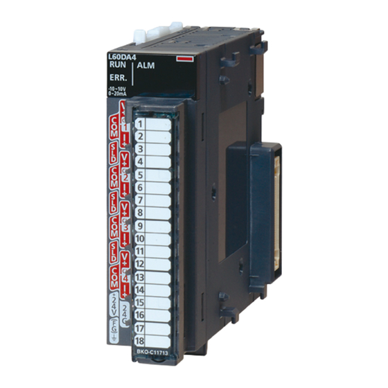
Chapter 2 Part Names
Part Names Overview
Identifies and describes the physical parts of the D/A converter module.
Chapter 3 Specifications
3.1 General Specifications
Describes general specifications for the D/A converter module.
3.2 Performance Specifications
Details the performance specifications of the D/A converter module.
Chapter 3 Specifications
3.2.1 Number of Parameter Settings
Explains the number of parameters that can be set for the D/A converter module.
Chapter 3 Specifications
3.3 Function List
Lists the various functions available for the D/A converter module.
Chapter 3 Specifications
3.4 I/O Signal List
Provides a list of input and output signals for the D/A converter module.
Chapter 3 Specifications
3.5 Buffer Memory List
Details the buffer memory addresses used by the D/A converter module.
Chapter 5 System Configuration
5.1 Overall System Configuration
Shows system configuration examples for using the D/A converter module.
Chapter 5 System Configuration
5.2 Applicable System
Refers to manuals for connectable modules and compatible software versions.
5.3 Restrictions When D/A Converter Module is Connected to Head Module
Describes restrictions when connecting the module to a head module.
Chapter 6 Installation and Wiring
6.1 Installation Environment and Installation Position
Provides precautions for the installation environment and position.
Chapter 6 Installation and Wiring
6.2 Terminal Block
Details precautions, signal names, and procedures for the terminal block.
Chapter 6 Installation and Wiring
6.3 Wiring
Shows wiring diagrams for voltage and current output to the terminal block.
Chapter 6 Installation and Wiring
6.4 External Wiring
Describes external wiring configurations for voltage and current output.
Chapter 7 Various Settings
7.1 Addition of Modules
Explains how to add the D/A converter module model name to the project.
Chapter 7 Various Settings
7.2 Switch Setting
Details setting the operation mode, HOLD/CLEAR, and output range for each channel.
Chapter 7 Various Settings
7.3 Parameter Setting
Covers setting parameters for each channel, including basic and warning output settings.
Chapter 7 Various Settings
7.4 Auto Refresh
Explains how to transfer data in buffer memory to specified devices.
Chapter 7 Various Settings
7.5 Offset/Gain Setting
Covers setting the offset/gain for user range configuration.
7.5.1 Setting from GX Works2 "Offset/Gain Setting"
Details the procedure for setting offset/gain using GX Works2.
Chapter 7 Various Settings
7.5 Offset/Gain Setting
Covers setting the offset/gain for user range configuration.
7.5.2 Setting from a Program
Describes how to set offset/gain by using a program.
Chapter 8 Functions
8.1 D/A Conversion Enable/Disable Function
Sets whether to enable or disable D/A conversion for each channel.
8.2 D/A Output Enable/Disable Function
Sets whether to output D/A conversion value or offset value for each channel.
Chapter 8 Functions
8.3 Analog Output HOLD/CLEAR Function
Sets whether to hold or clear the output analog value based on CPU status.
Chapter 8 Functions
8.4 Analog Output Test when CPU Module is in STOP Status
Explains how to perform analog output tests when the CPU module is in STOP status.
Chapter 8 Functions
8.5 Scaling Function
Converts digital values to scaled values for analog output.
Chapter 8 Functions
8.6 Alarm Output Function
Outputs an alarm when the digital value is outside the preset range.
Chapter 8 Functions
8.7 Error Log Function
Stores a history of errors and alarms that occurred in the D/A converter module.
Chapter 8 Functions
8.8 Module Error Collection Function
Collects errors and alarms into the CPU module or head module for data retention.
Chapter 8 Functions
8.9 Error Clear Function
Allows clearing errors from the system monitor or display unit.
Chapter 8 Functions
8.10 Saving and Restoring Offset/Gain Values
Enables saving and restoring offset/gain values for module replacement or configuration.
Chapter 9 Display Unit
9.1 Display Unit
Describes the LCD display unit attached to the CPU module for status checks.
9.2 Menu Structure
Shows the organization of the "MOD MON/TEST" and "MOD SETTINGS" menus.
Chapter 9 Display Unit
9.3 List of Setting Value Change Screens
Lists available screens for changing setting values, including input regulations.
Chapter 9 Display Unit
9.4 Checking and Clearing Errors
Explains how to check and clear errors using the display unit.
Chapter 10 Programming
10.1 Procedure for Programming
Outlines the steps to create a program for the D/A converter module.
Chapter 10 Programming
10.2 When Using a Standard System Configuration
Provides program examples for standard system configurations and usage conditions.
Chapter 10 Programming
10.3 When D/A Converter Module is Connected to Head Module
Describes system configuration and programming conditions when connecting to a head module.
Chapter 11 Troubleshooting
11.1 Checking on the Module Detailed Information
Details how to check errors by viewing module detailed information.
11.2 Checking by Latest Error Code (Un\G19)
Explains how to check error codes and alarm codes using the latest error code buffer memory.
11.3 Checking on the Module Error Collection Function
Describes checking errors collected by the module error collection function.
Chapter 11 Troubleshooting
11.4 Error Code List
Lists error codes, their descriptions, causes, and recommended actions.
Chapter 11 Troubleshooting
11.5 Alarm Code List
Lists alarm codes, their descriptions, causes, and recommended actions.
Chapter 11 Troubleshooting
11.6 Troubleshooting
Provides troubleshooting steps based on LED status and common issues.
Chapter 11 Troubleshooting
11.7 Checking the Status of D/A Converter Module by the System Monitor
Explains how to check module status, LED information, and hardware switch settings via the system monitor.
Appendices
Appendix 1 Details of I/O Signals
Describes the details of I/O signals for the D/A converter module.
Appendices
Appendix 1.1 Input Signal
Details input signals such as Module READY and External power supply READY flag.
Appendices
Appendix 1.2 Output Signal
Details output signals like CH Output enable/disable flag and Error clear request.
Appendices
Appendix 2 Details of Buffer Memory Addresses
Provides details on buffer memory addresses used by the D/A converter module.
Appendices
Appendix 3 I/O Conversion Characteristic of D/A Conversion
Explains the I/O conversion characteristics for voltage and current outputs.
Appendices
Appendix 4 D/A Conversion Accuracy
Describes the accuracy specifications for analog output values.
Appendices
Appendix 5 Dedicated Instruction
Lists the dedicated instructions that can be used with the D/A converter module.
Appendices
Appendix 5.1 Instruction List
Lists the dedicated instructions that can be used with the D/A converter module.
Appendix 5.2 G(P).OFFGAN
Explains the G(P).OFFGAN instruction for switching operation modes.
Appendices
Appendix 5.2 G(P).OFFGAN
Explains the G(P).OFFGAN instruction for switching operation modes.
Appendix 5.3 G(P).OGLOAD
Details the G(P).OGLOAD instruction for reading offset/gain values.
Appendices
Appendix 5.3 G(P).OGLOAD
Details the G(P).OGLOAD instruction for reading offset/gain values.
Appendix 5.4 G(P).OGSTOR
Details the G(P).OGSTOR instruction for restoring offset/gain values.
Appendix 6 Checking Serial Number and Function Version
Appendix 7 Differences with Q Series
Compares specifications between L60DA4 and Q64DAN, and LCPU and QCPU.
Appendix 8 When Using GX Developer or GX Configurator-DA
Appendix 8.1 Operation of GX Developer
Explains how to configure settings using GX Developer.
Appendix 8 When Using GX Developer or GX Configurator-DA
Appendix 8.1 Operation of GX Developer
Explains how to configure settings using GX Developer.
Appendix 8.2 Operation of GX Configurator-DA
Explains how to configure settings using GX Configurator-DA.
Warranty
Gratis Warranty Term and Range
Details the gratis warranty term, range, and conditions for repairs.
Onerous Repair Term After Discontinuation
Mentions repair acceptance for seven years after product discontinuation.
Overseas Service
States that overseas repairs are handled by local FA Centers.
Exclusion of Liability for Consequential Damages
Excludes liability for consequential damages and lost profits.
Product Specification Changes
Notes that specifications are subject to change without prior notice.
Need help?
Do you have a question about the MELSEC L60DA4 and is the answer not in the manual?
Questions and answers