Table of Contents
Advertisement
Quick Links
0290050/4
LCV3, LCV4, LCV6 and LCV7
Installation and Maintenance Instructions
IM-P029-17 ST Issue 4
Lift Check Valves
IM-P029-17
1. Safety information
2. General
product information
3. Installation
4. Commissioning
5. Operation
6. Spare parts and
Maintenance
© Copyright 2015
Printed in France
ST Issue 4
1
Advertisement
Table of Contents

Related Manuals for Spirax Sarco LCV3


Summary of Contents for Spirax Sarco LCV3
- Page 1 0290050/4 IM-P029-17 ST Issue 4 LCV3, LCV4, LCV6 and LCV7 Lift Check Valves Installation and Maintenance Instructions 1. Safety information 2. General product information 3. Installation 4. Commissioning 5. Operation 6. Spare parts and Maintenance © Copyright 2015 IM-P029-17 ST Issue 4...
- Page 2 IM-P029-17 ST Issue 4...
-
Page 3: Safety Information
1. Safety information Safe operation of these products can only be guaranteed if they are properly installed, commissioned, used and maintained by qualified personnel (see Section 1.11) in compliance with the operating instructions. General installation and safety instructions for pipeline and plant construction, as well as the proper use of tools and safety equipment must also be complied with. - Page 4 Connections Gases Gases Liquids Liquids DN15 to DN25 DN32 ASME 150 JIS / KS 10 LCV6 DN40 to DN50 PN16, PN25 and PN40 JIS / KS 20 Others DN65 to DN100 DN15 to DN25 ASME 250 DN32 to DN40 Others...
- Page 5 Determine the correct installation situation and direction of fluid flow. iv) Spirax Sarco products are not intended to withstand external stresses that may be induced by any system to which they are fitted. It is the responsibility of the installer to consider these stresses and take adequate precautions to minimise them.
-
Page 6: Protective Clothing
Ensure that any pressure is isolated and safely vented to atmospheric pressure before attempting to maintain the product, this is easily achieved by fitting Spirax Sarco depressurisation valves type DV (see separate literature for details) and consider double isolation (double block and bleed) and the locking or labelling of closed valves. -
Page 7: Returning Products
1.16 Returning products Customers and stockists are reminded that under EC Health, Safety and Environment Law, when returning products to Spirax Sarco they must provide information on any hazards and the precautions to be taken due to contamination residues or mechanical damage which may present a health, safet y or environmental risk. - Page 8 Prevention of water hammer Steam trapping on steam mains: 30 - 50 metre intervals Steam Trap set Steam Trap set Trap set Condensate Condensate Condensate Steam Mains - Do's and Don'ts: Flow Flow Steam Steam ...
- Page 9 Prevention of tensile stressing Pipe misalignment: Installing products or re-assembling after maintenance: Do not over tighten. Flange bolts should be gradually tightened across Use correct torque figures. diameters to ensure even load and alignment. Thermal expansion: Guides Axial movement Short Fixing point...
-
Page 10: General Product Information
2. General product information 2.1 General description The LCV3, LCV4, LCV6 and LCV7 lift check valves are designed in accordance with EN 12516 and ASME B16.34 to prevent reverse flow in the installations. Available types: LCV3 Cast iron bodied with stainless steel internals. - Page 11 Fig. 1 2.2 Sizes and pipe connections LCV6 LCV7 Unit PN40 ASME 150 BSP NPT PN16 ASME 125 JIS / KS 20 ASME 300 PN25 ASME 250 Connections JIS / KS 10 DN15 ½" • • • • • DN20 ¾"...
- Page 12 220°C @ 9.8 bar g (428°F @ 142 psi g) Minimum operating temperature 0°C (32°F) Note: For lower operating temperatures consult Spirax Sarco. Designed for a maximum cold hydraulic test pressure of: 20 bar g (290 psi g) IM-P029-17 ST Issue 4...
- Page 13 300°C @ 9.6 bar g (572°F @ 139 psi g) Minimum operating temperature -10°C (14°F) Note: For lower operating temperatures consult Spirax Sarco. Designed for a maximum cold hydraulic test pressure of: 24 bar g (348 psi g) Flanged ASME 125...
- Page 14 300 ° C @ 32 bar g (572°F @ 464 psi g) Minimum operating temperature 0°C (32°F) Note: For lower operating temperatures consult Spirax Sarco. Designed for a maximum cold hydraulic test pressure of: (739 psi g) 51 bar g...
- Page 15 400°C @ 23.8 bar g (752°F @ 345 psi g) temperature bolting Minimum operating temperature -10°C (14°F) Note: For lower operating temperatures consult Spirax Sarco. Designed for a maximum cold hydraulic test pressure of: 60 bar g (870 psi g) Flanged ASME 150...
- Page 16 2.3 Pressure / temperature limits - LCV6 Pressure psi g Steam saturation curve 49.6 Pressure bar g The product must not be used in this region. A - B Screwed NPT, socket weld and flanged ASME 300. A - C Screwed BSP and flanged EN 1092 PN40.
- Page 17 400°C @ 27.4 bar g (752°F @ 397 psi g) Minimum operating temperature -10°C (14°F) Note: For lower operating temperatures consult Spirax Sarco. Designed for a maximum cold hydraulic test pressure of: 60 bar g (870 psi g) Screwed NPT, Socket weld and Flanged ASME 300...
- Page 18 300°C @ 9.8 bar g (572°F @ 142 psi g) Minimum operating temperature 0°C (32°F) Note: For lower operating temperatures consult Spirax Sarco. Designed for a maximum cold hydraulic test pressure of: 20 bar g (290 psi g) IM-P029-17 ST Issue 4...
- Page 19 300°C @ 12.8 bar g (572°F @ 185 psi g) Minimum operating temperature -10°C (14°F) Note: For lower operating temperatures consult Spirax Sarco. Designed for a maximum cold hydraulic test pressure of: 24 bar g (348 psi g) Screwed BSP and Flanged EN 1092 PN25...
-
Page 20: Dimensions (Approximate)
2.4 Dimensions (approximate) in mm Please note: Flanged ASME versions are (approximate) in inches Dimension A Screwed Flanged Screwed Flanged Flanged PN40 ASME 125 ASME PN16 Connection LCV3 LCV7 Socket weld PN25 ASME JIS 10 / KS 10 JIS 20 / KS 20 DN15 ½"... -
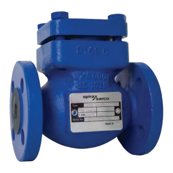
Page 21: Product Name-Plate
DN80 3" DN100 4" Fig. 2 2.5 Product name-plate Description Fig. 3 T max T min Code number 2.6 Weights (approximate) in kg LCV3 LCV4 LCV6 LCV7 Screwed Screwed Unit Flanged Screwed Flanged Socket Flanged Socket Flanged Screwed weld weld 4.30... -
Page 22: Installation
Section 2.4, minimum withdrawal distance 'C'. 3.11 Welding into the pipeline - LCV4 and LCV6 socket weld connections. For specific weld procedures consult the relevant National and International welding standards. Note: If a trap is to discharge to atmosphere ensure it is to a safe place as the discharging fluid may be at a temperature of 100°C (212°F). -
Page 23: Operation
4. Commissioning After installation or maintenance ensure that the system is fully functional. Carry out tests on any alarms or protective devices. 5. Operation LCV check valves are opened by the pressure of the fluid and closed by the spring as soon as the flow ceases and before the reverse flow occurs. -
Page 24: Spare Parts And Maintenance
Always order spares by using the description of the LCV and Spare 1 or Spare 2. Example: 1 off LCV Internals kit – Spare 2, for a Spirax Sarco DN15 LCV4 lift check valve having flanged EN 1092 PN40 connections. - Page 25 Fig. 6 IM-P029-17 ST Issue 4...
-
Page 26: Maintenance
Replace the internals - seat (4) and cage (9) after refitting the disc (6) and spring (7). Replace the cover (1) and the bolts (8) (for the LCV6 version you must lubricate the screws when refitting the bolt) and tighten to the recommended torque (see Table 1). - Page 27 Fig. 7 IM-P029-17 ST Issue 4...
- Page 28 IM-P029-17 ST Issue 4...
Need help?
Do you have a question about the LCV3 and is the answer not in the manual?
Questions and answers