Table of Contents
Advertisement
1000026/16
IM-P100-05
CTLS Issue 17
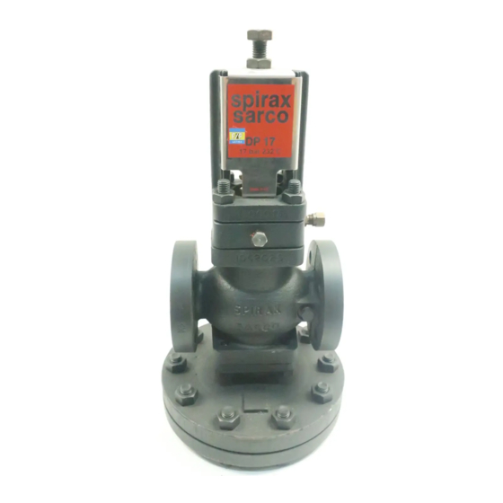
DP17, DP17E, DP17G, DP17R, DP17Y and DP27G
Pilot Operated Pressure Reducing Valves
Installation and Maintenance Instructions
1. Safety information
2. General product
information
3. Installation
4. Commissioning
5. Maintenance
6. Spare parts
7. Fault finding
© Copyright 2018
IM-P100-05 CTLS Issue 17
1
Printed in GB
Advertisement
Table of Contents


Need help?
Do you have a question about the DP17 and is the answer not in the manual?
Questions and answers