
Related Manuals for Strautmann Super-Vitesse CFS 3501


Summary of Contents for Strautmann Super-Vitesse CFS 3501
- Page 1 Translation of the Original Operating Instructions Short-cut forage wagon Short-cut forage wagon with dosing unit Super-Vitesse CFS 3101, 3501 Super-Vitesse CFS 3101 DO, 3501 DO 71600919 0.000 10.13...
- Page 2 EC Declaration of Conformity according to the EC machinery directive 2006/42/EC, Annex II, 1.A Manufacturer: B. Strautmann & Söhne GmbH u. Co. KG Bielefelder Str. 53 D-49196 Bad Laer Legal person established within the EC and authorized to compile the technical documentation: B.
- Page 3 © Copyright B. Strautmann & Söhne GmbH u. Co. KG, 2013 All rights reserved. Reproduction, even in excerpts, only allowed with the permission of B. Strautmann & Söhne GmbH u. Co. KG. Super-Vitesse CFS 3101, 3501 / Super-Vitesse CFS 3101 DO, 3501 DO 10.13...
- Page 4 Foreword Dear customer, You have decided in favour of a quality product from the large B. Strautmann & Söhne GmbH u. Co. KG product range. We thank you for the confidence you have shown in us. Upon receipt of the machine, please check for transport damage or missing parts! Check the delivered machine for its completeness, including the ordered optional extras, by means of the delivery note.
-
Page 5: Table Of Contents
3.6.1 Warning signs 39 3.6.2 Instruction signs 44 3.6.3 Placing of warning and instruction signs 46 Risks in case of non-observance of safety instructions and warning signs 47 Super-Vitesse CFS 3101, 3501 / Super-Vitesse CFS 3101 DO, 3501 DO 10.13... - Page 6 5.14.2 Uncouple propeller shaft from tractor 76 5.15 Brake system 77 5.15.1 Dual-line compressed-air brake system 77 5.15.1.1 Dual-line compressed-air brake system with mechanical automatic load- sensitive brake (ALB) regulator 77 Super-Vitesse CFS 3101, 3501 / Super-Vitesse CFS 3101 DO, 3501 DO 10.13...
- Page 7 Display information in Working menu 118 7.2.3 Functions and their symbols 119 7.2.4 Set machine parameters 133 7.2.4.1 Call up SET menu 134 7.2.4.2 Set machine model 135 Super-Vitesse CFS 3101, 3501 / Super-Vitesse CFS 3101 DO, 3501 DO 10.13...
- Page 8 12.6.4 Rotor gear of cutting unit 173 12.6.5 Angular switchgear of cutting unit 173 12.6.6 Angular gear of CFS unit 174 12.6.7 Angular gear of dosing unit 174 12.6.8 Check/Top up oil level 174 Super-Vitesse CFS 3101, 3501 / Super-Vitesse CFS 3101 DO, 3501 DO 10.13...
- Page 9 12.16.9 Check brake 203 12.16.10 Check automatic slack adjuster 203 12.17 Maintenance of Bogie chassis 204 12.18 Tightening torques 204 13 Malfunctions and remedy 206 13.1 Hydraulics 206 13.2 Electrics 207 Super-Vitesse CFS 3101, 3501 / Super-Vitesse CFS 3101 DO, 3501 DO 10.13...
- Page 10 14.5 Electronics – Easy-to-use and ISOBUS control – Sensors 218 14.6 Electronics – Easy-to-use and ISOBUS control – Control unit 220 14.7 Connection of lighting system 222 14.8 Connection of additional electrical loads 222 Super-Vitesse CFS 3101, 3501 / Super-Vitesse CFS 3101 DO, 3501 DO 10.13...
-
Page 11: User Information
Numbers in parentheses refer to position numbers in figures. The first number refers to the figure, the second number to the position number in the figure. Example (Fig. 3/6): Figure 3, Position 6 Super-Vitesse CFS 3101, 3501 / Super-Vitesse CFS 3101 DO, 3501 DO 10.13... -
Page 12: Applied Terms
… the component of an operating element system which is directly actuated by the operator, e. g. by pressing. An operating element may be an adjusting lever, a key button, rotary switch, key etc. Super-Vitesse CFS 3101, 3501 / Super-Vitesse CFS 3101 DO, 3501 DO 10.13... -
Page 13: Product Description
The machines are available with various optional extras. Due to the individual equipment of your machine, not all descriptions included in these operating instructions apply to your machine. Optional extras are marked in these operating instructions and are available at extra cost. Super-Vitesse CFS 3101, 3501 / Super-Vitesse CFS 3101 DO, 3501 DO 10.13... -
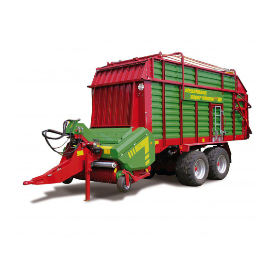
Page 14: Overview - Assemblies
Product description Overview – Assemblies Fig. 1 Super-Vitesse CFS 3101, 3501 / Super-Vitesse CFS 3101 DO, 3501 DO 10.13... -
Page 15: Safety And Protective Devices
Close open protective devices before powering the machine. Super-Vitesse CFS 3101, 3501 / Super-Vitesse CFS 3101 DO, 3501 DO 10.13... - Page 16 Product description Fig. 2 Super-Vitesse CFS 3101, 3501 / Super-Vitesse CFS 3101 DO, 3501 DO 10.13...
-
Page 17: Supply Lines Between Tractor And Machine
Fig. 3 2.3.1 Marking of hydraulic supply lines Hydraulic connector "Flow line" Label Arrows: white Background: red Hydraulic connector "Return line" Label Arrows: white Background: blue Super-Vitesse CFS 3101, 3501 / Super-Vitesse CFS 3101 DO, 3501 DO 10.13... - Page 18 P: Pressure pipe (red) T: Tank line (blue) Load-sensing connector Label Explanation of the following symbols: Load-sensing connector (blue) Hydraulic brake system (red) Super-Vitesse CFS 3101, 3501 / Super-Vitesse CFS 3101 DO, 3501 DO 10.13...
-
Page 19: Traffic-Related Equipment
Fig. 4 (1) Warning plates (5) License plate (2) Side reflectors (4 on each side of machine) (6) Speed sign (3) Chocks (7) Triangular reflectors (4) Multi-function light Super-Vitesse CFS 3101, 3501 / Super-Vitesse CFS 3101 DO, 3501 DO 10.13... -
Page 20: Correct Use
Within the hazardous area, risks occur at dangerous spots which cannot be completely eliminated due to the operational safety of the machine. The risks exist permanently or may occur unexpectedly. Super-Vitesse CFS 3101, 3501 / Super-Vitesse CFS 3101 DO, 3501 DO 10.13... -
Page 21: Type Plate And Ce Symbol
The complete marking is treated as a document and must not be altered or made unrecognizable. (1) Type plate with CE symbol (2) Vehicle/Machine ID number (embossed into the frame) (3) ALB plate Fig. 5 Super-Vitesse CFS 3101, 3501 / Super-Vitesse CFS 3101 DO, 3501 DO 10.13... -
Page 22: License Plate
40 km/h: 255 mm x 130 mm. for machines with an admissible maximum speed of more than 40 km/h: 340 mm x 200 mm. Super-Vitesse CFS 3101, 3501 / Super-Vitesse CFS 3101 DO, 3501 DO 10.13... -
Page 23: Technical Data
In case of equipment with bottom hitch and K 80 coupling head (up to 40 km/h) the tongue load and the gross vehicle weight rating are increased by 1000 kg. Figures, technical data and weights may change due to technical development and are not binding for delivery. Super-Vitesse CFS 3101, 3501 / Super-Vitesse CFS 3101 DO, 3501 DO 10.13... -
Page 24: Tyre Pressure
Product description 2.9.1 Tyre pressure Tyre pressures for tandem axle (22.5“) Super-Vitesse CFS 3101, 3501 / Super-Vitesse CFS 3101 DO, 3501 DO 10.13... -
Page 25: Required Tractor Equipment
Thus, a free return line reduces heating-up of the hydraulic oil. The hydraulic hose pipes are marked by colours at the hydraulic plugs, see chapter „Marking of hydraulic supply lines“, page 17. Super-Vitesse CFS 3101, 3501 / Super-Vitesse CFS 3101 DO, 3501 DO 10.13... -
Page 26: Noise Specifications
The workplace-related emission value (sound pressure level) is 74.0 dB(A), measured during operating mode at the driver's ear, the cabin being closed. The sound pressure level mainly depends on the tractor used. Super-Vitesse CFS 3101, 3501 / Super-Vitesse CFS 3101 DO, 3501 DO 10.13... -
Page 27: Safety Instructions
DIN EN 388, safety footwear, protective clothing, skin protectant, etc. 3.2.2 Operator’s obligation Any members of staff charged to operate the machine are obliged: to acquaint themselves with the machine before starting operation, Super-Vitesse CFS 3101, 3501 / Super-Vitesse CFS 3101 DO, 3501 DO 10.13... -
Page 28: Qualification Of Staff
A person is considered to be instructed if he or she has been informed about the tasks assigned to him or her and possible risks in case of improper behaviour and if he or she has been Super-Vitesse CFS 3101, 3501 / Super-Vitesse CFS 3101 DO, 3501 DO 10.13... -
Page 29: Product Safety
The manufacturer will not assume any liability for damage resulting from: unauthorized alterations of the machine, non-approved modification and accessory parts, welding and drilling work on load-bearing parts of the machine. Super-Vitesse CFS 3101, 3501 / Super-Vitesse CFS 3101 DO, 3501 DO 10.13... -
Page 30: Spare And Wearing Parts, Auxiliary Materials
Particularly be aware of children! Never carry passengers, animals or objects on the machine! Carrying passengers and transport of animals or objects are not allowed on the machine! Super-Vitesse CFS 3101, 3501 / Super-Vitesse CFS 3101 DO, 3501 DO 10.13... - Page 31 Wear close-fitting clothing! Loose-fitting clothing increases the risk of becoming entangled in or wound up at drive shafts! Start the machine only if all protective devices have been installed and are in protective position! Super-Vitesse CFS 3101, 3501 / Super-Vitesse CFS 3101 DO, 3501 DO 10.13...
-
Page 32: Hydraulic System
The respective movement must automatically stop as soon as the operating element is released. This shall not apply to: continuous movements of devices, Super-Vitesse CFS 3101, 3501 / Super-Vitesse CFS 3101 DO, 3501 DO 10.13... -
Page 33: Electrical System
2004/108/EC as amended from time to time and bear the CE symbol! Never fit the machine with additional work lights without authorisation! The manufacturer will not assume any liability or warranty for subsequent damage on the electrical system. Super-Vitesse CFS 3101, 3501 / Super-Vitesse CFS 3101 DO, 3501 DO 10.13... -
Page 34: Propeller Shaft Operation
Secure tractor and machine against accidental starting and rolling before carrying out any maintenance, cleaning, lubrication or setup work on machines powered by propeller shafts or before hitching/unhitching them! Super-Vitesse CFS 3101, 3501 / Super-Vitesse CFS 3101 DO, 3501 DO 10.13... -
Page 35: Hitched Machines
Cover the tractor's hose couplings before carrying out journeys without machine! Hang the couplings of the feed and brake line on the provided blank connections with the machine unhitched! Super-Vitesse CFS 3101, 3501 / Super-Vitesse CFS 3101 DO, 3501 DO 10.13... -
Page 36: Axles
Climbing onto the transport floor is not allowed as long as the tractor engine is running! Passengers are not allowed on the machine! Unhitch the machine from the tractor only when empty! Super-Vitesse CFS 3101, 3501 / Super-Vitesse CFS 3101 DO, 3501 DO 10.13... -
Page 37: Service And Maintenance Of Machine
are marked by the triangular hazard symbol and a preceding signal word. The signal word refers to the seriousness of the risk. Super-Vitesse CFS 3101, 3501 / Super-Vitesse CFS 3101 DO, 3501 DO 10.13... -
Page 38: Important Information
INFORMATION marks user hints and particularly useful information. This information will help you to use all functions of your machine in the best possible way. Super-Vitesse CFS 3101, 3501 / Super-Vitesse CFS 3101 DO, 3501 DO 10.13... -
Page 39: Warning And Instruction Signs
Make sure that people leave the hazardous area of the machine before moving machine parts." Super-Vitesse CFS 3101, 3501 / Super-Vitesse CFS 3101 DO, 3501 DO 10.13... - Page 40 This risk may cause most serious injuries or even death. Never enter the cargo space as long as the tractor engine is running with the propeller shaft coupled/the hydraulic/electronic system connected. Super-Vitesse CFS 3101, 3501 / Super-Vitesse CFS 3101 DO, 3501 DO 10.13...
- Page 41 Secure the machine against accidental rolling before unhitching the machine from the tractor or before parking the machine. Use the parking brake and/or the chock(s) for this purpose. Super-Vitesse CFS 3101, 3501 / Super-Vitesse CFS 3101 DO, 3501 DO 10.13...
- Page 42 This risk may cause most serious injuries including loss of limbs. Never open nor remove protective devices as long as the tractor engine is running with the propeller shaft coupled/the hydraulic/electronic system connected. Super-Vitesse CFS 3101, 3501 / Super-Vitesse CFS 3101 DO, 3501 DO 10.13...
- Page 43 drilling at the chassis, boring up of existing holes at the chassis frame or at load-bearing parts, welding on load-bearing parts. Super-Vitesse CFS 3101, 3501 / Super-Vitesse CFS 3101 DO, 3501 DO 10.13...
-
Page 44: Instruction Signs
Risk due to improper cleaning of the machine. Absolutely observe the information in the chapter "Cleaning of machine", page 168 when using a pressure washer/steam blaster for cleaning the machine. Super-Vitesse CFS 3101, 3501 / Super-Vitesse CFS 3101 DO, 3501 DO 10.13... - Page 45 87010288 This pictograph illustrates fixing points for lifting equipment (jack). 87010285 Close the stop-cock (position 0) to secure the tailgate before carrying out work beneath the lifted tailgate. Super-Vitesse CFS 3101, 3501 / Super-Vitesse CFS 3101 DO, 3501 DO 10.13...
-
Page 46: Placing Of Warning And Instruction Signs
Safety instructions 3.6.3 Placing of warning and instruction signs The following figures illustrate the position of the warning and instruction signs on the machine. Fig. 9 Super-Vitesse CFS 3101, 3501 / Super-Vitesse CFS 3101 DO, 3501 DO 10.13... -
Page 47: Risks In Case Of Non-Observance Of Safety Instructions And Warning Signs
If the machine is equipped with a compressed-air brake system, you are only allowed to start moving the machine when the pressure gauge on the tractor indicates 5.0 bar. Super-Vitesse CFS 3101, 3501 / Super-Vitesse CFS 3101 DO, 3501 DO 10.13... - Page 48 Use appropriate slings which are able to safely carry the machine’s weight. Never stand within the lifting zone beneath the lifted machine. Fig. 11 (1) Spacer Super-Vitesse CFS 3101, 3501 / Super-Vitesse CFS 3101 DO, 3501 DO 10.13...
-
Page 49: Design And Function
Dangerous spots exist within the area of the pick-up due to functional reasons. Fig. 12 Fig. 13 Super-Vitesse CFS 3101, 3501 / Super-Vitesse CFS 3101 DO, 3501 DO 10.13... -
Page 50: Pick-Up Drive
(8) leading to the pick-up. The friction clutch (9) protects the powertrain leading to the pick-up against damage in case of overload and temporary torque peaks at the pick- Fig. 15 Super-Vitesse CFS 3101, 3501 / Super-Vitesse CFS 3101 DO, 3501 DO 10.13... -
Page 51: Silage Additive Pump
Risk of being drawn in and becoming entangled by the powered pick-up! Never use the machine without holding-down device with pulley (1), as holding-down-device and pulley also serve as a protective device. Super-Vitesse CFS 3101, 3501 / Super-Vitesse CFS 3101 DO, 3501 DO 10.13... -
Page 52: Feeder Rotor
Strippers (5) protrude into the gaps between the conveying tines (6) of the feeder rotor thus preventing the feeder rotor from becoming clogged. Fig. 17 Super-Vitesse CFS 3101, 3501 / Super-Vitesse CFS 3101 DO, 3501 DO 10.13... -
Page 53: Cutting Unit
The knife bag (1) for unused cutting knives or spare cutting knives is positioned at the right- hand front of the axle support close to the parking brake. Fig. 20 Super-Vitesse CFS 3101, 3501 / Super-Vitesse CFS 3101 DO, 3501 DO 10.13... -
Page 54: Transport Floor
The feed rate of the transport floor depends on the set filling degree. Observe the information in the chapter "Pre-select filling degree of loaded material in cargo space", page 136. Super-Vitesse CFS 3101, 3501 / Super-Vitesse CFS 3101 DO, 3501 DO 10.13... -
Page 55: Load-Protection Bars With Integrated Automatic Charging System
Low filling degree = smaller deflection of sensing band High filling degree = larger deflection of sensing band Auto ● Sensing band in upper switch position → The automatic charging system is switched Super-Vitesse CFS 3101, 3501 / Super-Vitesse CFS 3101 DO, 3501 DO 10.13... -
Page 56: Isobus Control Of Automatic Charging System
The switching plate releases an electrical pressure switch and disconnects the automatic charging system and the hydraulic drive of the transport floor. The control set simultaneously displays the message "Forage wagon full". Super-Vitesse CFS 3101, 3501 / Super-Vitesse CFS 3101 DO, 3501 DO 10.13... -
Page 57: Tailgate
The hydraulic cylinders only come into operation at the last moment to close the tailgate and lower it vertically onto the locking pin for being locked. Fig. 26 Super-Vitesse CFS 3101, 3501 / Super-Vitesse CFS 3101 DO, 3501 DO 10.13... -
Page 58: Crossover Conveyor (Optional Extra)
Fig. 28 Stop-cock Tailgate Activity 0 - closed lifted and locked trouble-shooting, cleaning, service and maintenance work I - open not locked charging discharging lifting and lowering possible Super-Vitesse CFS 3101, 3501 / Super-Vitesse CFS 3101 DO, 3501 DO 10.13... -
Page 59: Dosing Drums
Access door (1), ladder (2) and handle (3) permit access to the cargo space. The locking mechanism (4) secures the closed access door and the folded-up ladder in transport position. Fig. 30 Super-Vitesse CFS 3101, 3501 / Super-Vitesse CFS 3101 DO, 3501 DO 10.13... -
Page 60: Hydraulic System Of Machine
"Required tractor equipment", page 25. For information about the hose markings, refer to the chapter "Marking of hydraulic supply lines", page 17. (1) Hose holder for proper deposition of supply lines. Fig. 31 Super-Vitesse CFS 3101, 3501 / Super-Vitesse CFS 3101 DO, 3501 DO 10.13... -
Page 61: Electro-Hydraulic Control Block
Optional: (4) End plate with directional seat valves for steering axle (5) End plate with directional seat valves for tridem lift axle (not available here) Fig. 33 Super-Vitesse CFS 3101, 3501 / Super-Vitesse CFS 3101 DO, 3501 DO 10.13... -
Page 62: Load-Sensing Hydraulic System
Disconnect the load-sensing control line from the load-sensing connector of the tractor before operating the machine with free pressure regulator. Super-Vitesse CFS 3101, 3501 / Super-Vitesse CFS 3101 DO, 3501 DO 10.13... -
Page 63: Electrical System - Emergency Manual Operation
Use a blunt object (3) to push in the armature of the solenoid at the respective control valve to actuate the required hydraulic functions. Intermediate plates (4) and end plates (5): Screw in the knurled screw (6) at the required directional control/seat valve. Super-Vitesse CFS 3101, 3501 / Super-Vitesse CFS 3101 DO, 3501 DO 10.13... -
Page 64: Functional Diagram For Emergency Manual Operation
Design and function 5.9.1.3 Functional diagram for emergency manual operation (X)Y12 (X)Y13 (X)Y1 (X)Y2 (X)Y3 (X)Y9 (X)Y10 (X)Y4 (X)Y6 (X)Y7 (X)Y7 (X)Y22 (X)Y21 Super-Vitesse CFS 3101, 3501 / Super-Vitesse CFS 3101 DO, 3501 DO 10.13... - Page 65 1. Screw in the knurled screws (1, 2) at the directional seat valves (X)Y12 and (X)Y13. 2. Use a blunt object to push in the armature of the solenoid (X)Y31 (3). The cutting unit retracts. 3. Unscrew the knurled screws completely again. Super-Vitesse CFS 3101, 3501 / Super-Vitesse CFS 3101 DO, 3501 DO 10.13...
-
Page 66: Hydraulic Hose Pipes
Check the assignment of the hydraulic hose pipes at the control block of the machine if the coloured markings (dust caps) are missing: P = Pressure line T (R;S) = Return line Super-Vitesse CFS 3101, 3501 / Super-Vitesse CFS 3101 DO, 3501 DO 10.13... -
Page 67: Disconnect Hydraulic Hose Pipes
(only in case of bottom linkage) with dual-line compressed-air brake system and mechanical automatic load-sensitive brake pressure regulator a hydro-pneumatic tandem chassis with hydraulic levelling system: with follow-up steering Super-Vitesse CFS 3101, 3501 / Super-Vitesse CFS 3101 DO, 3501 DO 10.13... -
Page 68: Bogie Tandem Chassis
The shell/drawbar lug must be fixed to the coupling device of the tractor free of clearance if possible, such that the forced steering axle can properly work. Super-Vitesse CFS 3101, 3501 / Super-Vitesse CFS 3101 DO, 3501 DO 10.13... -
Page 69: Lock Forced Steering Axle
The steering axle is locked in "Straight" position. If the symbol is flashing, the steering axle could not be completely locked. Check the steering system. Super-Vitesse CFS 3101, 3501 / Super-Vitesse CFS 3101 DO, 3501 DO 10.13... -
Page 70: Drawbar
87. Properly hitch the machine to the tractor and secure it. Never use damaged or deformed trailer systems. Super-Vitesse CFS 3101, 3501 / Super-Vitesse CFS 3101 DO, 3501 DO 10.13... -
Page 71: Bolt-Type Coupling
Lubricate the area between the holding-down device and the surface of the shell as well. (1) Shorter holding-down device for ball-type coupling Fig. 40 Super-Vitesse CFS 3101, 3501 / Super-Vitesse CFS 3101 DO, 3501 DO 10.13... -
Page 72: Uncouple Drawbar
5. Lower the supporting leg to support position such that the shell disengages from the ball head. 6. Move the tractor forward (approx. 25 cm). 7. Secure tractor and machine against accidental starting and rolling. Super-Vitesse CFS 3101, 3501 / Super-Vitesse CFS 3101 DO, 3501 DO 10.13... -
Page 73: Drawbar Suspension For Folding Drawbar
When lowering the supporting leg, keep sufficient safe distance to the supporting leg as long as parts are moving. The machine is equipped with a mechanical supporting leg, which supports the unhitched machine. Super-Vitesse CFS 3101, 3501 / Super-Vitesse CFS 3101 DO, 3501 DO 10.13... -
Page 74: Lift Mechanical Supporting Leg To Transport Position
6. Lower the machine via the hydraulic folding drawbar until the machine rests on the supporting leg. The folding drawbar no longer transmits any Fig. 43 tongue load to the tractor. Super-Vitesse CFS 3101, 3501 / Super-Vitesse CFS 3101 DO, 3501 DO 10.13... -
Page 75: Propeller Shaft
Before switching the propeller shaft on, observe the safety instructions for propeller shaft operation. Super-Vitesse CFS 3101, 3501 / Super-Vitesse CFS 3101 DO, 3501 DO 10.13... -
Page 76: Couple Propeller Shaft To Tractor
Clean and lubricate the propeller shaft before longer downtimes. 1. Pull the propeller shaft locking mechanism off the tractor's p.t.o.shaft. 2. Place the propeller shaft onto the respective holder (1). Fig. 45 Super-Vitesse CFS 3101, 3501 / Super-Vitesse CFS 3101 DO, 3501 DO 10.13... -
Page 77: Brake System
ALB regulator has not been properly set! The setting dimension (L) at the ALB regulator must not be modified. The setting dimension (L) must correspond to the value indicated on the WABCO-ALB plate. Super-Vitesse CFS 3101, 3501 / Super-Vitesse CFS 3101 DO, 3501 DO 10.13... - Page 78 (11) Test connection in front of ALB regulator (12) Test connection behind ALB regulator (13) Test connection, diaphragm brake cylinder (14) Test connection, compressed-air reservoir (15) Parking brake Fig. 46 Super-Vitesse CFS 3101, 3501 / Super-Vitesse CFS 3101 DO, 3501 DO 10.13...
-
Page 79: Dual-Line Compressed-Air Brake System With Hydraulic Automatic Load-Sensitive Brake Pressure (Alb) Regulator
(8) Hydraulic cylinders of the hydraulic levelling system (9) Compressed-air reservoir (10) Drain valve (11) Test connection, compressed-air reservoir (12) Test connection, diaphragm brake cylinder (13) Parking brake Fig. 47 Super-Vitesse CFS 3101, 3501 / Super-Vitesse CFS 3101 DO, 3501 DO 10.13... -
Page 80: Braking Axle
4. Remove the hose coupling of the feed line (red) from the blank connection. 5. Properly fix the hose coupling of the feed line (red) to the red marked coupling device at the tractor. Super-Vitesse CFS 3101, 3501 / Super-Vitesse CFS 3101 DO, 3501 DO 10.13... -
Page 81: Disconnect Brake And Feed Line
The controlled hydraulic service brake system is connected to the special brake valve of the tractor. If the brake pedal on the tractor is pressed, the machine is slowed down. (1) Hydraulic sleeve ISO 5676 Fig. 49 Super-Vitesse CFS 3101, 3501 / Super-Vitesse CFS 3101 DO, 3501 DO 10.13... -
Page 82: Emergency Brake Valve
2. Secure tractor and machine against accidental rolling by means of the parking brake. The emergency brake valve does not replace the parking brake! 3. Remove the ripcord from the tractor. Super-Vitesse CFS 3101, 3501 / Super-Vitesse CFS 3101 DO, 3501 DO 10.13... -
Page 83: Connect Hydraulic Brake System
(2). 2. Couple the machine's hydraulic sleeve to the tractor's hydraulic plug of the hydraulic brake system. 3. Release the parking brake of the machine. Fig. 52 Super-Vitesse CFS 3101, 3501 / Super-Vitesse CFS 3101 DO, 3501 DO 10.13... -
Page 84: Disconnect Hydraulic Brake System
1. Swivel the crank handle (1) from resting position (3) by 180° to adjusting position (2). 2. Turn the crank handle clockwise. The parking brake is applied via the cable (5). Super-Vitesse CFS 3101, 3501 / Super-Vitesse CFS 3101 DO, 3501 DO 10.13... -
Page 85: Commissioning
This shall not apply to movements of devices: in continuous action for constant loads, with automatic control, which, for functional reasons, require an open-centre or pressing position. Super-Vitesse CFS 3101, 3501 / Super-Vitesse CFS 3101 DO, 3501 DO 10.13... -
Page 86: Check Tractor's Compatibility
the tractor's empty weight, the ballasting mass, the tongue load of the hitched machine. Super-Vitesse CFS 3101, 3501 / Super-Vitesse CFS 3101 DO, 3501 DO 10.13... -
Page 87: Preconditions For The Operation Of Tractors With Rigid Drawbar Trailers
ISO 5692-1 Draw pin (Piton-Fix) Drawbar lug (hitch ring) ISO 6489-4 ISO 5692-1 4000 kg ≤ 40 km/h Ball-type coupling 80 Shell 80 2000 kg > 40 km/h Super-Vitesse CFS 3101, 3501 / Super-Vitesse CFS 3101 DO, 3501 DO 10.13... -
Page 88: Calculate Actual D Value For Combination To Be Coupled
[t] without tongue load Gravitational acceleration (9.81 m/s²) Actual calculated D value for the Specified D values of the tractor's coupling combination device and the machine's drawgear Super-Vitesse CFS 3101, 3501 / Super-Vitesse CFS 3101 DO, 3501 DO 10.13... -
Page 89: Calculate Tractor's Admissible Towing Capacity
Due to the D value of the tractor's coupling device, the admissible axle load is 14.5 t. This calculated axle load must not be exceeded when charging your rigid drawbar trailer. Super-Vitesse CFS 3101, 3501 / Super-Vitesse CFS 3101 DO, 3501 DO 10.13... -
Page 90: Mount Body Side Panels, Ropes And Body Tarpaulin
Two people are required for mounting the attachment sections, ropes and the body tarpaulin. Fig. 55 Positions of tubular supports Super-Vitesse CFS 3101 3101 DO 3501 3501 DO Super-Vitesse CFS 3101, 3501 / Super-Vitesse CFS 3101 DO, 3501 DO 10.13... - Page 91 5. Screw the side panel extensions (3) to the tubular supports (1). 6. Swivel the upper front grating (4) and the load-protection bars (5) up. On machines without beaters 12. Mount the tarpaulin (1). Fig. 57 Super-Vitesse CFS 3101, 3501 / Super-Vitesse CFS 3101 DO, 3501 DO 10.13...
- Page 92 17. Put the other end (3) of the rope through the loop (2). Fig. 59 18. Pull the ropes from the bottom through the eyes of the central tubular support. Fig. 60 Super-Vitesse CFS 3101, 3501 / Super-Vitesse CFS 3101 DO, 3501 DO 10.13...
-
Page 93: Mount Control Set On The Tractor
25 A. The feed line of the 3-pole socket must have a minimum cable cross section of 4 mm Super-Vitesse CFS 3101, 3501 / Super-Vitesse CFS 3101 DO, 3501 DO 10.13... -
Page 94: Adjust Mounting Height Of Folding Drawbar
X is not 1180 mm. Use the rear borehole of the respective screw-on seat (1) if you cannot reach the required distance X, in particular in case of bottom linkage. Fig. 64 Super-Vitesse CFS 3101, 3501 / Super-Vitesse CFS 3101 DO, 3501 DO 10.13... -
Page 95: Adjust Length Of Propeller Shaft To Tractor
Adjustment of the propeller shaft length is allowed if observing the required minimum transverse contact ratio. Structural alterations to the propeller shaft which are not specified in the included operating instructions for the propeller shaft are not allowed. Super-Vitesse CFS 3101, 3501 / Super-Vitesse CFS 3101 DO, 3501 DO 10.13... - Page 96 7. Reinsert the shortened propeller shaft halves into each other. 8. Lubricate the p.t.o. shaft of the tractor and the propeller shaft of the machine before coupling the propeller shaft. Super-Vitesse CFS 3101, 3501 / Super-Vitesse CFS 3101 DO, 3501 DO 10.13...
-
Page 97: Mount Shell To Folding Drawbar
(3). 5.5 Press the lamp bracket (1) down Fig. 70 again. 6. Unlock the tailgate from its closed position: 6.1 Always use one hand to hold the Super-Vitesse CFS 3101, 3501 / Super-Vitesse CFS 3101 DO, 3501 DO 10.13... - Page 98 (9). 15. Insert the locking tubes (11) at the bottom of the crossover conveyor. Fig. 71 16. Remove the locking bolt from each locating hook (12). Super-Vitesse CFS 3101, 3501 / Super-Vitesse CFS 3101 DO, 3501 DO 10.13...
- Page 99 23. Activate the crossover conveyor at the ISOBUS control set if necessary. The crossover conveyor is ready for use and is operated via the ISOBUS control set. Fig. 73 Super-Vitesse CFS 3101, 3501 / Super-Vitesse CFS 3101 DO, 3501 DO 10.13...
-
Page 100: Dismount Crossover Conveyor
(12) and swivel it to the ground. 5.4 Insert the locking bolt (13) into each locating hook (12). 5.5 Insert the locking tubes (11) at the top of the crossover conveyor. Fig. 75 Super-Vitesse CFS 3101, 3501 / Super-Vitesse CFS 3101 DO, 3501 DO 10.13... -
Page 101: Check Machine For Proper Functioning
Check the machine for proper functioning before the first startup and each time before starting work: 1. Hitch the machine to the tractor. 2. Completely lubricate the machine and the propeller shaft. Observe the information in the chapter "Lubrication of machine", page 169. Super-Vitesse CFS 3101, 3501 / Super-Vitesse CFS 3101 DO, 3501 DO 10.13... -
Page 102: Start-Up After Longer Downtime
CFS drum, in order to ensure its proper functioning, see chapter "Bleed friction and compensating clutch of CFS drum", page 177. Super-Vitesse CFS 3101, 3501 / Super-Vitesse CFS 3101 DO, 3501 DO 10.13... -
Page 103: Operation
The symbols above the operating elements identify the executable functions. After an operating element has been actuated, the power unit triggers the corresponding solenoid valve at the electro-hydraulic control block Super-Vitesse CFS 3101, 3501 / Super-Vitesse CFS 3101 DO, 3501 DO 10.13... - Page 104 In case of longer downtimes of the machine, switch the control set off, in order to avoid a discharging of the tractor’s battery due to switched- on loads! Super-Vitesse CFS 3101, 3501 / Super-Vitesse CFS 3101 DO, 3501 DO 10.13...
-
Page 105: Functions Of The Easy-To-Use Control
● the functions "Open tailgate" and "Lift folding drawbar" can be carried out simultaneously, ● the functions "Open tailgate" and "Lower folding drawbar" cannot be carried out simultaneously. Super-Vitesse CFS 3101, 3501 / Super-Vitesse CFS 3101 DO, 3501 DO 10.13... -
Page 106: Switch Road Travel Mode On
H1 ("Road travel mode active") is flashing, ● the states are indicated by the control lamps H2 ("Tailgate open"“), H4 ("Steering axle locked") and H5 ("Cargo space full"). Super-Vitesse CFS 3101, 3501 / Super-Vitesse CFS 3101 DO, 3501 DO 10.13... -
Page 107: Switch Operating Mode On
The operating mode is switched on. The control lamp H1 ("Operating mode active") lights up. 7.1.2.3 Switch machine off ● Toggle switch in lower switch position The machine is switched off. Super-Vitesse CFS 3101, 3501 / Super-Vitesse CFS 3101 DO, 3501 DO 10.13... -
Page 108: Switch Work Lights On/Off
If the loaded material piling up deflects the sensing band (1) upwards, the hydraulic drive of the transport floor Fig. 81 Super-Vitesse CFS 3101, 3501 / Super-Vitesse CFS 3101 DO, 3501 DO 10.13... -
Page 109: Switch Transport Floor On (Level I)
Toggle switch in upper switch position As long as the lever is kept in its upper switch position, the transport floor will move at the set feed rate. Super-Vitesse CFS 3101, 3501 / Super-Vitesse CFS 3101 DO, 3501 DO 10.13... -
Page 110: Double Feed Rate Of Transport Floor For Complete Emptying (Level Ii)
I and II. ● Control dial to "1" = low feed rate of transport floor. ● Control dial to "10" = high feed rate of transport floor. Super-Vitesse CFS 3101, 3501 / Super-Vitesse CFS 3101 DO, 3501 DO 10.13... -
Page 111: Open Tailgate
○ On forage wagons equipped with beaters: The control lamp H2 ("Tailgate open") goes out as soon as the tailgate is below position I. Super-Vitesse CFS 3101, 3501 / Super-Vitesse CFS 3101 DO, 3501 DO 10.13... -
Page 112: Lift Folding Drawbar
One or several cutting knives retracted from the conveyor duct Swivel the cutting unit completely out of the conveyor duct and in again with the feeder rotor running. Super-Vitesse CFS 3101, 3501 / Super-Vitesse CFS 3101 DO, 3501 DO 10.13... -
Page 113: Extend Cutting Unit
● Key button in lower switch position The control lamp H4 ("Steering axle locked") lights up. The steering axle is locked in "Straight" position. Super-Vitesse CFS 3101, 3501 / Super-Vitesse CFS 3101 DO, 3501 DO 10.13... -
Page 114: Lift Pick-Up
The ISOBUS control set is automatically switched on and off when the tractor ignition is turned on and off. In case of longer downtimes of the machine, additionally disconnect the mobile tractor connecting cable. Super-Vitesse CFS 3101, 3501 / Super-Vitesse CFS 3101 DO, 3501 DO 10.13... - Page 115 (8) to carry out the selected functions. Individual sensors (3) determine the respective operating state of the selected assembly, e. g. Steering axle locked or Steering axle unlocked. The operating states are graphically shown on the screen (9). Super-Vitesse CFS 3101, 3501 / Super-Vitesse CFS 3101 DO, 3501 DO 10.13...
- Page 116 11) (10) Double feed rate of transport floor for complete emptying (transport floor level II)/Increase feed rate of transport floor Fig. 83 during discharge (in combination with key Super-Vitesse CFS 3101, 3501 / Super-Vitesse CFS 3101 DO, 3501 DO 10.13...
- Page 117 (18) Retract cutting unit (19) Extend cutting unit (20) Lock steering axle (21) Unlock steering axle (22) Lift pick-up (23) Lower pick-up to open-centre position/ no open-centre position (rigid) Fig. 84 Super-Vitesse CFS 3101, 3501 / Super-Vitesse CFS 3101 DO, 3501 DO 10.13...
-
Page 118: Display Information In Working Menu
(12) Operating state "Crossover conveyor ccw rotation on/cw rotation/stop", here "Crossover conveyor cw rotation on" (13) Operating state "Silage additive pump on/off", here "Silage additive pump on" Super-Vitesse CFS 3101, 3501 / Super-Vitesse CFS 3101 DO, 3501 DO 10.13... -
Page 119: Functions And Their Symbols
Working menu appear: (1) Warning message (2) Pick-up down (3) Tailgate lifted (4) Transport floor powered (5) Dosing drums powered Super-Vitesse CFS 3101, 3501 / Super-Vitesse CFS 3101 DO, 3501 DO 10.13... - Page 120 (optional extra) are switched off, the work lights (optional extra) are switched on if the work lights were on when carrying out the function "Switch on road travel mode". Super-Vitesse CFS 3101, 3501 / Super-Vitesse CFS 3101 DO, 3501 DO 10.13...
- Page 121 The Discharge mode A II is automatically switched off when the tailgate is lowered. During discharge, the transport floor feed can be switched on and off as often as desired by pressing the key. Super-Vitesse CFS 3101, 3501 / Super-Vitesse CFS 3101 DO, 3501 DO 10.13...
- Page 122 With the dosing drums powered, the "Dosing drums On" symbol appears. With the transport floor powered, the "Feed On" symbol is permanently lit. Super-Vitesse CFS 3101, 3501 / Super-Vitesse CFS 3101 DO, 3501 DO 10.13...
- Page 123 The "Automatic charging system on" symbol appears. The screen shows: 2. Press the key again. The automatic charging system is switched off. The "Automatic charging system off" symbol appears. Super-Vitesse CFS 3101, 3501 / Super-Vitesse CFS 3101 DO, 3501 DO 10.13...
- Page 124 The screen shows: 1. Press the key once during discharge. The feed rate of the transport floor is doubled. The symbols "Double set feed rate" and "Double feed" appear. Super-Vitesse CFS 3101, 3501 / Super-Vitesse CFS 3101 DO, 3501 DO 10.13...
- Page 125 The transport floor starts running and conveys the loaded material away from the dosing drums for a maximum time of 3 seconds. The "Reverse feed" symbol appears. Super-Vitesse CFS 3101, 3501 / Super-Vitesse CFS 3101 DO, 3501 DO 10.13...
- Page 126 the lighting is automatically switched on if the road travel mode is switched off. Super-Vitesse CFS 3101, 3501 / Super-Vitesse CFS 3101 DO, 3501 DO 10.13...
- Page 127 "Tailgate lifted" symbol appears. Lift tailgate (Machine with dosing drums) When discharging on the bunker silo, the tailgate is automatically lifted to the set first opening width after pressing the key. Super-Vitesse CFS 3101, 3501 / Super-Vitesse CFS 3101 DO, 3501 DO 10.13...
- Page 128 1. Press the key until the "Cutting unit" symbol is in "Cutting unit retracted" position and a beep is emitted. The cutting unit is retracted from the conveyor duct. Super-Vitesse CFS 3101, 3501 / Super-Vitesse CFS 3101 DO, 3501 DO 10.13...
- Page 129 When switching the control set on, the single-acting steering axle is always in unlocked condition. Super-Vitesse CFS 3101, 3501 / Super-Vitesse CFS 3101 DO, 3501 DO 10.13...
- Page 130 In Discharge mode A I, the steering axle is automatically locked at speeds up to 12 km/h. In the case of the electro-hydraulic forced steering axle system, the key has a touch-control design. Super-Vitesse CFS 3101, 3501 / Super-Vitesse CFS 3101 DO, 3501 DO 10.13...
- Page 131 The "Steering axle locked" symbol appears and a beep is emitted. If the symbol is flashing, the steering axle could not be completely locked. Check the steering system. Super-Vitesse CFS 3101, 3501 / Super-Vitesse CFS 3101 DO, 3501 DO 10.13...
- Page 132 The steering axle is locked in "Straight" position. If the symbol is flashing, the steering axle could not be completely locked. Check the steering system. Super-Vitesse CFS 3101, 3501 / Super-Vitesse CFS 3101 DO, 3501 DO 10.13...
-
Page 133: Set Machine Parameters
The machine parameters are set in the SET menu. Depending on the machine model and the machine's equipment, the indicated symbols may differ. The arrow in the centre indicates which parameter may currently be changed. Super-Vitesse CFS 3101, 3501 / Super-Vitesse CFS 3101 DO, 3501 DO 10.13... -
Page 134: Call Up Set Menu
Right: Entry whether equipped with dosing drums or not; here "with dosing drums" (7) Entry of steering axle model (8) Vacant (9) Display of total number of service hours Super-Vitesse CFS 3101, 3501 / Super-Vitesse CFS 3101 DO, 3501 DO 10.13... -
Page 135: Set Machine Model
3. Press the key to change the setting. Observe the fact that the setting "BPW" must be selected both for BPW and FAD axles with single-acting hydraulic cylinders! Super-Vitesse CFS 3101, 3501 / Super-Vitesse CFS 3101 DO, 3501 DO 10.13... -
Page 136: Pre-Select Filling Degree Of Loaded Material In Cargo Space
Two people are required for calibration of the automatic charging system. One person moves the sensing band in the cargo space, while the other person operates the control set on the tractor. Super-Vitesse CFS 3101, 3501 / Super-Vitesse CFS 3101 DO, 3501 DO 10.13... -
Page 137: Operating Hours Counter, Service Hours Counter And Transported Loads Counter
These counters must be reset manually. The total service hours counter, the total operating hours counter and the total transported loads counter cannot be reset. Super-Vitesse CFS 3101, 3501 / Super-Vitesse CFS 3101 DO, 3501 DO 10.13... -
Page 138: Call Up Counter Menu
The screen shows: 1. Briefly press the key once. The Counter menu appears. 2. Press and hold the key once. The daily service hours counter and the Super-Vitesse CFS 3101, 3501 / Super-Vitesse CFS 3101 DO, 3501 DO 10.13... -
Page 139: Sensor And State Overview
The display shows the Sensor and status overview: (1) Sensor number (2) Sensor status (3) Number of sensor circuits 2. Press the key to display the next or preceding sensor. Super-Vitesse CFS 3101, 3501 / Super-Vitesse CFS 3101 DO, 3501 DO 10.13... -
Page 140: Ses System
The SES system: controls depending on the speed, informs about malfunctions of the steering system via acoustic and visual warning messages on the control set, Super-Vitesse CFS 3101, 3501 / Super-Vitesse CFS 3101 DO, 3501 DO 10.13... -
Page 141: Steering Computer Displays
Error message; an active error has been detected xxx-xxx-xx If several active errors are detected, the respective error messages will be displayed one after the other. Super-Vitesse CFS 3101, 3501 / Super-Vitesse CFS 3101 DO, 3501 DO 10.13... -
Page 142: Error Diagnosis
5. Press the key once. The details referring to the selected error message are successively displayed. 6. Press the key once. The Error diagnosis menu is exited. Super-Vitesse CFS 3101, 3501 / Super-Vitesse CFS 3101 DO, 3501 DO 10.13... -
Page 143: Hitch And Unhitch Machine
Observe the course of the supply lines during hitching. The supply lines: must easily give way to any movements during cornering without any stress, buckling or chafing, must not chafe against external components. Super-Vitesse CFS 3101, 3501 / Super-Vitesse CFS 3101 DO, 3501 DO 10.13... -
Page 144: Unhitch Machine
6. Disconnect the brake system. Observe the information in the chapter "Disconnect brake and feed line", page 81. 7. Uncouple the propeller shaft. Observe the information in the chapter "Uncouple propeller shaft from tractor", page 76. 8. Disconnect the lighting system. Super-Vitesse CFS 3101, 3501 / Super-Vitesse CFS 3101 DO, 3501 DO 10.13... -
Page 145: Settings
make sure that third persons (children) leave the tractor, secure lifted machine parts against accidental lowering. Super-Vitesse CFS 3101, 3501 / Super-Vitesse CFS 3101 DO, 3501 DO 10.13... -
Page 146: Pick-Up
Spindle unscrewed = Additional roller feelers carry more weight Spindle screwed in = Additional roller feelers carry less weight Super-Vitesse CFS 3101, 3501 / Super-Vitesse CFS 3101 DO, 3501 DO 10.13... -
Page 147: Set Holding-Down Device With Pulley
Make sure that people leave the swivelling range of the carriers for the holding-down device with pulley before setting the distance between pick-up and holding-down device. Super-Vitesse CFS 3101, 3501 / Super-Vitesse CFS 3101 DO, 3501 DO 10.13... -
Page 148: Set Cutting Length
40 cutting knives at one level ensure a cutting length of 39 mm. For information about removal and installation of cutting knives, see chapter "Remove and install cutting knives", page 182. Super-Vitesse CFS 3101, 3501 / Super-Vitesse CFS 3101 DO, 3501 DO 10.13... -
Page 149: Use Of Machine
Risk to people due to failure of components if the machine is powered at inadmissible high drive speed! Observe the admissible drive speed of the machine before switching the tractor's p.t.o. shaft on. Super-Vitesse CFS 3101, 3501 / Super-Vitesse CFS 3101 DO, 3501 DO 10.13... -
Page 150: Charging
Risk of becoming entangled, wound up and being drawn in within the area of the movable pick-up components! Make sure that people leave the pick-up area before switching the pick-up drive on. Super-Vitesse CFS 3101, 3501 / Super-Vitesse CFS 3101 DO, 3501 DO 10.13... - Page 151 136. Observe the visual and acoustic signals of the control set during charging. Observe the maximum admissible load capacity of the machine. Super-Vitesse CFS 3101, 3501 / Super-Vitesse CFS 3101 DO, 3501 DO 10.13...
-
Page 152: Charging With Easy-To-Use Control
Road travel mode on the field. 1. Press the 2. Press the key once to switch on the automatic charging system. 3. Press the key once if necessary to lower the folding drawbar. Super-Vitesse CFS 3101, 3501 / Super-Vitesse CFS 3101 DO, 3501 DO 10.13... -
Page 153: Determine Admissible Loading Capacity
"Technical data", page 23. Max. admissible load = Admissible axle load - Empty weight Max. load [kg] Max. admissible loading capacity Specific weight of loaded material [kg/m Super-Vitesse CFS 3101, 3501 / Super-Vitesse CFS 3101 DO, 3501 DO 10.13... -
Page 154: Bulk Densities Of Different Materials
6. Keep hold of switch (7) in the upper position until the tailgate is open. The control lamp (H2) lights up. 7 Set switch (6) to the upper position to switch on the transport floor. Super-Vitesse CFS 3101, 3501 / Super-Vitesse CFS 3101 DO, 3501 DO 10.13... -
Page 155: Machine Equipped With Beaters
"Forage wagon full"! The beaters may become clogged if the feed rate for the transport floor is not reduced. Super-Vitesse CFS 3101, 3501 / Super-Vitesse CFS 3101 DO, 3501 DO 10.13... - Page 156 If the folding drawbar is equipped with a drawbar suspension, lower the folding drawbar just as far as to ensure that the hydraulic cylinders of the folding drawbar are still extended by approx. 20 mm. Super-Vitesse CFS 3101, 3501 / Super-Vitesse CFS 3101 DO, 3501 DO 10.13...
-
Page 157: Discharging With Isobus Control
For changing the feed rate, press the key once and the key quickly in succession several times if necessary. Press the key to lower the folding drawbar during discharge on the bunker silo. Super-Vitesse CFS 3101, 3501 / Super-Vitesse CFS 3101 DO, 3501 DO 10.13... -
Page 158: Machine Equipped With Beaters
The dosing drums start to run and after a short delay, the transport floor automatically starts. 6.1 Switch the tractor's p.t.o. shaft immediately off if the slip clutch responds. 6.2 Press the key to switch the transport floor feed function off. Super-Vitesse CFS 3101, 3501 / Super-Vitesse CFS 3101 DO, 3501 DO 10.13... - Page 159 The Discharge modes A I and A II are deactivated and the transport floor is automatically switched off. 11. Drive off the bunker silo. Super-Vitesse CFS 3101, 3501 / Super-Vitesse CFS 3101 DO, 3501 DO 10.13...
-
Page 160: Eliminate Clogging At The Pick-Up And The Feeder Rotor
Secure tractor and machine against accidental starting and rolling before manually eliminating clogging/blockages. 1. Switch the p.t.o. shaft off. 2. Secure tractor and machine against accidental starting and rolling. 3. Eliminate the clogging/blockages.. Super-Vitesse CFS 3101, 3501 / Super-Vitesse CFS 3101 DO, 3501 DO 10.13... -
Page 161: Secure Tractor And Machine Against Accidental Starting And Rolling
on extremely uneven ground or downhill gradients by means of the parking brake and the chocks. Super-Vitesse CFS 3101, 3501 / Super-Vitesse CFS 3101 DO, 3501 DO 10.13... -
Page 162: Transport Journeys
With the Road Travel mode switched on: the Road Travel menu appears, apart from the functions "Lock steering axle" and "Unlock steering axle", all other functions on the control set are disabled, Super-Vitesse CFS 3101, 3501 / Super-Vitesse CFS 3101 DO, 3501 DO 10.13... -
Page 163: Transport Journeys With Partly Discharged Machine
(max. 3 seconds) for this purpose. Observe the fact that the driving characteristics of the tractor are influenced by the load, in particular if the machine is partly empty. Super-Vitesse CFS 3101, 3501 / Super-Vitesse CFS 3101 DO, 3501 DO 10.13... -
Page 164: Service And Maintenance Of Machine
In case of higher loads and amount of stress, maintenance work must be carried out at respectively shorter intervals. This shall in particular apply to the brakes and chassis. Modifications to the maintenance instructions shall be reserved! Super-Vitesse CFS 3101, 3501 / Super-Vitesse CFS 3101 DO, 3501 DO 10.13... - Page 165 Risk of crushing and impact to people due to accidental lowering of the lifted tailgate. Secure the lifted tailgate against accidental lowering by means of the stop- cock before entering the hazardous area beneath the lifted tailgate. Super-Vitesse CFS 3101, 3501 / Super-Vitesse CFS 3101 DO, 3501 DO 10.13...
-
Page 166: Service And Maintenance Plan - Overview
Drain the compressed-air reservoir of the compressed-air brake system via the drain valve. Use compressed air to clean the cutting unit, in particular the retainer of the cutting knives and the knife security system. Super-Vitesse CFS 3101, 3501 / Super-Vitesse CFS 3101 DO, 3501 DO 10.13... - Page 167 Have the hydraulic hose pipes checked for their operational safety by an expert. After end of season Remove al cutting knives. Grease or lubricate all movable parts of the cutting unit and the machine. Super-Vitesse CFS 3101, 3501 / Super-Vitesse CFS 3101 DO, 3501 DO 10.13...
-
Page 168: Enter Cargo Space
Lubricate the machine after cleaning, especially after cleaning by means of a pressure washer/steam blaster or fat dissolving agents. Continuously inspect the machine for corrosion damage! Remedy corrosion damage by touching up paintwork. Super-Vitesse CFS 3101, 3501 / Super-Vitesse CFS 3101 DO, 3501 DO 10.13... -
Page 169: Lubrication Of Machine
Observe the included sub-supplier documentation for lubrication of the propeller shaft(s)! Super-Vitesse CFS 3101, 3501 / Super-Vitesse CFS 3101 DO, 3501 DO 10.13... -
Page 170: Lubrication Plan
Service and maintenance of machine 12.4.1 Lubrication plan Fig. 94 Super-Vitesse CFS 3101, 3501 / Super-Vitesse CFS 3101 DO, 3501 DO 10.13... -
Page 171: Preservation/Longer Downtimes
50 service hours, then every 500 or 2000 service hours, at least once a year (depending on which change interval limit occurs first). Super-Vitesse CFS 3101, 3501 / Super-Vitesse CFS 3101 DO, 3501 DO 10.13... -
Page 172: Feed Gearing Of Transport Floor
(2) Oil filling screw (3) Oil drain plug Fig. 95 12.6.3 Main gearbox of cutting unit (1) Oil inspection plug (2) Oil filling screw (3) Oil drain plug Fig. 96 Super-Vitesse CFS 3101, 3501 / Super-Vitesse CFS 3101 DO, 3501 DO 10.13... -
Page 173: Rotor Gear Of Cutting Unit
12.6.5 Angular switchgear of cutting unit Check the oil level with the pick-up lowered. (1) Oil inspection plug (2) Oil filling screw (3) Oil drain plug Fig. 98 Super-Vitesse CFS 3101, 3501 / Super-Vitesse CFS 3101 DO, 3501 DO 10.13... -
Page 174: Angular Gear Of Cfs Unit
2. Unscrew the oil inspection plug. The oil must be visible at the oil inspection plug. 3. Top up gear lubricant oil through the oil filler neck if necessary. Super-Vitesse CFS 3101, 3501 / Super-Vitesse CFS 3101 DO, 3501 DO 10.13... -
Page 175: Change Gear Lubricant Oil
The easiest way to bleed the stuck friction clutch is to charge the machine with material to be loaded for a short time with the groove nut unscrewed such that the stuck friction clutch slips for a short time. Super-Vitesse CFS 3101, 3501 / Super-Vitesse CFS 3101 DO, 3501 DO 10.13... - Page 176 Torque of friction clutch: 900-1000 Nm 12. Lock the groove nut. 13. Fix the protective casing of the pick-up to the machine by means of the two screws. Fig. 102 Super-Vitesse CFS 3101, 3501 / Super-Vitesse CFS 3101 DO, 3501 DO 10.13...
-
Page 177: Check/Retighten Tension Of Roller Chain For Pick-Up Drive
Bleed friction and compensating clutch of CFS drum The friction and compensating clutch must be bled before the first start-up and after longer downtimes to ensure its proper functioning. Super-Vitesse CFS 3101, 3501 / Super-Vitesse CFS 3101 DO, 3501 DO 10.13... -
Page 178: Remove/Mount Friction And Compensating Clutch Of Cfs Drum
10. Mount the friction and overrunning clutch in reverse order. 11. Close the right-hand movable side protector Fig. 106 and lock it in protective position. Super-Vitesse CFS 3101, 3501 / Super-Vitesse CFS 3101 DO, 3501 DO 10.13... -
Page 179: Align Switch Rods With Respect To The Switch Levers Of The Angular Switchgear (Only When Equipped With Dosing Drums)
It is not allowed to power the feeder rotor with the side protector being open. Close the left-hand movable side protector before powering the feeder rotor. Super-Vitesse CFS 3101, 3501 / Super-Vitesse CFS 3101 DO, 3501 DO 10.13... -
Page 180: Check / Retighten Tension Of Roller Chain For Feeder Rotor Drive
Risk of crushing and shearing when swivelling the cover plate! Use the handle when swivelling the cover plate. Make sure that people leave the hazardous area on the opposite side before swivelling the cover plate. Super-Vitesse CFS 3101, 3501 / Super-Vitesse CFS 3101 DO, 3501 DO 10.13... -
Page 181: Clean Cutting Unit
2.1 Take off the spring (5) at the outer ring (6) of the knife holder by means of the mounting lever. The lever pocket falls down and the Fig. 110 roller can be accessed. Super-Vitesse CFS 3101, 3501 / Super-Vitesse CFS 3101 DO, 3501 DO 10.13... -
Page 182: Remove And Install Cutting Knives
4. Secure tractor and machine against accidental starting and rolling. 5. Pull the bolt (1) out. 6. Fold the cover plate (2) down. Fig. 112 7. Wear protective goggles. Super-Vitesse CFS 3101, 3501 / Super-Vitesse CFS 3101 DO, 3501 DO 10.13... - Page 183 11. Insert the knife lever into the boreholes of the cutting knife. 12. Pull the locking lever (6) up and lift the cutting knife out of the knife holder. Fig. 114 Super-Vitesse CFS 3101, 3501 / Super-Vitesse CFS 3101 DO, 3501 DO 10.13...
-
Page 184: Install Cutting Knives
13. Extend the cutting unit into the conveyor duct via the control set. 11. Lower the pick-up. 14. Lower the folding drawbar. 12. Switch the tractor's p.t.o. shaft on. Pick-up and feeder rotor are powered. Super-Vitesse CFS 3101, 3501 / Super-Vitesse CFS 3101 DO, 3501 DO 10.13... -
Page 185: Grind Cutting Knives
Fig. 117 width of the rotor. Super-Vitesse CFS 3101, 3501 / Super-Vitesse CFS 3101 DO, 3501 DO 10.13... -
Page 186: Check Distance Between Strippers And Rotor
The distance must not fall below the minimum value. Reasons for a too small distance between strippers and rotor are: worn strippers or deformed stripper holders. Super-Vitesse CFS 3101, 3501 / Super-Vitesse CFS 3101 DO, 3501 DO 10.13... -
Page 187: Set "Cutting Unit Retracted" Sensor
Secure tractor and machine against accidental starting and rolling before setting the "Cutting unit retracted" sensor. Super-Vitesse CFS 3101, 3501 / Super-Vitesse CFS 3101 DO, 3501 DO 10.13... -
Page 188: Transport Floor
Fig. 122 The chains of the transport floor: are automatically pre-tightened, must be tightened equally, but not too firmly, are only allowed to sag slightly. Super-Vitesse CFS 3101, 3501 / Super-Vitesse CFS 3101 DO, 3501 DO 10.13... -
Page 189: Shorten And Tighten Transport Floor Chain
14. Close the access door. 15. Fold the ladder up. 16. Lock the ladder and the access door by means of the locking mechanism. 17. Use the stop-cock to unlock the tailgate. Super-Vitesse CFS 3101, 3501 / Super-Vitesse CFS 3101 DO, 3501 DO 10.13... -
Page 190: Lubricate Chain Tensioners And Deflection Points Of Transport Floor
3. Close the protective devices and lock them in protective position. 12.12.2 Check/Retighten tension of roller chains of dosing drums The roller chains must be retightened if they can be pushed in by more than 5 mm. Super-Vitesse CFS 3101, 3501 / Super-Vitesse CFS 3101 DO, 3501 DO 10.13... - Page 191 3.3 Retighten the tightening wheel bolt. 4. Lubricate the respective roller chain by means of grease or engine oil. 5. Close the protective devices and lock them in protective position. Super-Vitesse CFS 3101, 3501 / Super-Vitesse CFS 3101 DO, 3501 DO 10.13...
-
Page 192: Hydraulic System
Depressurize the hydraulic system before carrying out work on the hydraulic system. 1. Relieve the respective hydraulic cylinder via the corresponding operating element with the hydraulic pump switched off. Super-Vitesse CFS 3101, 3501 / Super-Vitesse CFS 3101 DO, 3501 DO 10.13... -
Page 193: Depressurise Folding Drawbar With Drawbar Suspension
(14/04 = year/month = April 2014) (3) Maximum admissible operating pressure (210 bar) Fig. 127 After expiration of the period of use, the hydraulic hose pipe must no longer be used. Super-Vitesse CFS 3101, 3501 / Super-Vitesse CFS 3101 DO, 3501 DO 10.13... -
Page 194: Inspection Criteria For Hydraulic Hose Pipes
Replacement of the hydraulic filter is not allowed with the hydraulic system being under operating pressure. Only replace the hydraulic filter when the hydraulic system of the machine is not connected to the tractor. Super-Vitesse CFS 3101, 3501 / Super-Vitesse CFS 3101 DO, 3501 DO 10.13... -
Page 195: Tyres
Store "loose" tyres at a dark place, free of oil and other chemicals. Do not let tyres come near electric motors. The ozone produced by the electric motors slowly dessicates the rubber. Super-Vitesse CFS 3101, 3501 / Super-Vitesse CFS 3101 DO, 3501 DO 10.13... -
Page 196: Change Tyres
3. Tighten the wheel nuts at the required tightening torque. 4. Check the wheel nuts for tightness after 10 service hours. Retighten wheel nuts if necessary Fig. 130 Super-Vitesse CFS 3101, 3501 / Super-Vitesse CFS 3101 DO, 3501 DO 10.13... -
Page 197: Brake System
5. Clean the filter element with benzene or thinner (rinse). 6. Use compressed air to blow the filter element dry. 7. Reinsert the filter element into the hose coupling. Fig. 132 8. Close the cover. Super-Vitesse CFS 3101, 3501 / Super-Vitesse CFS 3101 DO, 3501 DO 10.13... -
Page 198: Set Compressed-Air Brake System
5 mm in case of riveted linings, 2 mm in case of glued linings. 4. Replace the brake linings if necessary. Fig. 134 Super-Vitesse CFS 3101, 3501 / Super-Vitesse CFS 3101 DO, 3501 DO 10.13... -
Page 199: Maintenance Of Axles
Check automatic slack adjuster for proper functioning. * Also after each change of brake linings. ** Also after each wheel change. Relubricate all lubrication points after cleaning the machine by means of pressure washers. Super-Vitesse CFS 3101, 3501 / Super-Vitesse CFS 3101 DO, 3501 DO 10.13... -
Page 200: Lubricate Knuckle Arm Bearing
Make sure that no grease or oil enters the brake system! Depending on the series, the cam bearing may not be sealed on the brake side. Fig. 139 Super-Vitesse CFS 3101, 3501 / Super-Vitesse CFS 3101 DO, 3501 DO 10.13... -
Page 201: Lubricate Standard Slack Adjuster
Actuate the brake lever again several times if necessary. Fig. 142 5. Retighten the adjusting screw. 6. Reinstall the cap and lubricate with long-life grease one more time. Super-Vitesse CFS 3101, 3501 / Super-Vitesse CFS 3101 DO, 3501 DO 10.13... -
Page 202: Tighten Wheel Nuts
Release the brake. Place two levers between tyres and ground and check the bearing clearance. If there is a noticeable bearing clearance, have it readjusted (shop work!). Fig. 144 Super-Vitesse CFS 3101, 3501 / Super-Vitesse CFS 3101 DO, 3501 DO 10.13... -
Page 203: Check Brake Linings
→ The gear coupling must audibly engage and the adjusting screw slightly turns clockwise during the return stroke. 4. Retighten the adjusting screw. Fig. 146 5. Reinstall the rubber cap and lubricate with long-life grease. Super-Vitesse CFS 3101, 3501 / Super-Vitesse CFS 3101 DO, 3501 DO 10.13... -
Page 204: Maintenance Of Bogie Chassis
Fig. 147 12.18 Tightening torques These tightening torques are reference values. Differing data specified elsewhere in the operating instructions or the included sub- supplier documentation shall always prevail! Super-Vitesse CFS 3101, 3501 / Super-Vitesse CFS 3101 DO, 3501 DO 10.13... - Page 205 Tighten gear or crown nuts at full torque. Shear bolts are designed such that they shear off (break) at a certain stress. Only use bolts of equal quality when replacing shear bolts. Super-Vitesse CFS 3101, 3501 / Super-Vitesse CFS 3101 DO, 3501 DO 10.13...
-
Page 206: Malfunctions And Remedy
Too little hydraulic power in Hydraulic plugs too small Provide appropriately large load-sensing mode hydraulic plugs Load-sensing control pressure Possibly use pressure too low intensifier; consult the manufacturer Super-Vitesse CFS 3101, 3501 / Super-Vitesse CFS 3101 DO, 3501 DO 10.13... -
Page 207: Electrics
Defective wiring (short-circuit) Check wires, replace them if not show a status message on necessary the control set Sensor not properly set Adjust sensor Defective sensor Replace sensor Super-Vitesse CFS 3101, 3501 / Super-Vitesse CFS 3101 DO, 3501 DO 10.13... -
Page 208: Working
Cutting knives bent Align or replace cutting knives Slip clutch of pick-up responds Pick-up set too low Readjust setting frequently Pick-up heavily soiled in its Clean pick-up interior Super-Vitesse CFS 3101, 3501 / Super-Vitesse CFS 3101 DO, 3501 DO 10.13... - Page 209 Plug screw at level block not Tighten plug screw tightened Unequal load of axle one and Possibly adjust travelling height Super-Vitesse CFS 3101, 3501 / Super-Vitesse CFS 3101 DO, 3501 DO 10.13...
-
Page 210: Circuit Diagrams
Circuit diagrams Circuit diagrams 14.1 Hydraulics Super-Vitesse CFS 3101, 3501 / Super-Vitesse CFS 3101 DO, 3501 DO 10.13... - Page 211 (8) Throttle (only machines equipped with beaters) (9) Cutting unit (10) Steering axle (FAD) (11) Steering axle (BPW) (optional extra) (12) Crossover conveyor (optional extra) (X) Only mounted with crossover conveyor (optional extra) Super-Vitesse CFS 3101, 3501 / Super-Vitesse CFS 3101 DO, 3501 DO 10.13...
-
Page 212: Hydraulics - Forced Steering Axle System
14.2 Hydraulics – Forced steering axle system Hand pump Stop-cock Pressure gauge Membrane accumulator 60 bar Steering cylinder, left-hand Steering cylinder, right-hand Master cylinder, left-hand Master cylinder, right-hand Super-Vitesse CFS 3101, 3501 / Super-Vitesse CFS 3101 DO, 3501 DO 10.13... - Page 213 Circuit diagrams This page has intentionally been left blank. Super-Vitesse CFS 3101, 3501 / Super-Vitesse CFS 3101 DO, 3501 DO 10.13...
-
Page 214: Electronics - Easy-To-Use And Isobus Control - Cable Harness Overview
Circuit diagrams 14.3 Electronics – Easy-to-use and ISOBUS control – Cable harness overview Super-Vitesse CFS 3101, 3501 / Super-Vitesse CFS 3101 DO, 3501 DO 10.13... - Page 215 (4) Pre-selection Y31 (5) Proportional (6) Return line of transport floor (7) Pre-selection Y30 (8) Steering axle (9) Folding drawbar (10) Tailgate (11) Pick-up (12) Cutting unit (13) Central lubrication Super-Vitesse CFS 3101, 3501 / Super-Vitesse CFS 3101 DO, 3501 DO 10.13...
-
Page 216: Electronics - Easy-To-Use And Isobus Control - Valves
Circuit diagrams 14.4 Electronics – Easy-to-use and ISOBUS control – Valves Super-Vitesse CFS 3101, 3501 / Super-Vitesse CFS 3101 DO, 3501 DO 10.13... - Page 217 16/42 Ground, transport floor level II 27/42 Ground, valves 4 28/42 Tailgate 29/42 Folding drawbar 30/42 Ground, silage additive pump 41/42 Ground, valves 3 42/42 Ground, valves 2 Super-Vitesse CFS 3101, 3501 / Super-Vitesse CFS 3101 DO, 3501 DO 10.13...
-
Page 218: Electronics - Easy-To-Use And Isobus Control - Sensors
Circuit diagrams 14.5 Electronics – Easy-to-use and ISOBUS control – Sensors Super-Vitesse CFS 3101, 3501 / Super-Vitesse CFS 3101 DO, 3501 DO 10.13... - Page 219 Tailgate completely lifted Speed, beaters, left-hand Speed, beaters, right-hand Potentiometer, automatic charging system Knife protection system (transmitter) Knife protection system (receiver) Machine is full Pressure switch Axle unlocked Super-Vitesse CFS 3101, 3501 / Super-Vitesse CFS 3101 DO, 3501 DO 10.13...
-
Page 220: Electronics - Easy-To-Use And Isobus Control - Control Unit
Circuit diagrams 14.6 Electronics – Easy-to-use and ISOBUS control – Control unit Super-Vitesse CFS 3101, 3501 / Super-Vitesse CFS 3101 DO, 3501 DO 10.13... - Page 221 E2 Work light, rear, left-hand E3 Work light, rear, right-hand E4 Work lights (optional extra) E5 Warning beacon (optional extra) E6 Work lights, front grating E7 Work lights, rear Super-Vitesse CFS 3101, 3501 / Super-Vitesse CFS 3101 DO, 3501 DO 10.13...
-
Page 222: Connection Of Lighting System
Additional electrical loads are e. g. a silage additive pump or additional lighting (more than 2 lamps). We offer an additional control for additional loads which triggers these additional loads via relays. Super-Vitesse CFS 3101, 3501 / Super-Vitesse CFS 3101 DO, 3501 DO 10.13... - Page 223 Remove and install cutting knives ... 182 Set sensor ..........187 Calibration ........... 136 Automatic charging system (ISOBUS DC value ............88 control) ..........136 Delivery rate ..........25 Cargo space lighting ........126 Super-Vitesse CFS 3101, 3501 / Super-Vitesse CFS 3101 DO, 3501 DO 10.13...
- Page 224 Replace hydraulic filter ......194 Operation ............ 103 Service and maintenance ......192 Esay-to-use control........103 ISOBUS control ........114 Overload clutch ........... 150 Instruction signs ..........44 ISOBUS control .......... 114 Super-Vitesse CFS 3101, 3501 / Super-Vitesse CFS 3101 DO, 3501 DO 10.13...
- Page 225 Warning signs ..........39 Design ............140 Warranty ............30 Error diagnosis ......... 142 Wheel nuts Error message ......... 141 Tightening torques ........202 Steering computer displays ..... 141 Super-Vitesse CFS 3101, 3501 / Super-Vitesse CFS 3101 DO, 3501 DO 10.13...
Need help?
Do you have a question about the Super-Vitesse CFS 3501 and is the answer not in the manual?
Questions and answers