Advertisement
POINT I/O
Use this document to install and wire the following components of your POINT
Interface: 1734-ADN, -PDN
POINT I/O modules have no switches to set. You set module parameters with a software configuration tool. To obtain EDS files for use in
configuration, go to: http://www.ab.com/networks/eds
This product installation information is also available at: http://www.ab.com/manuals/io/
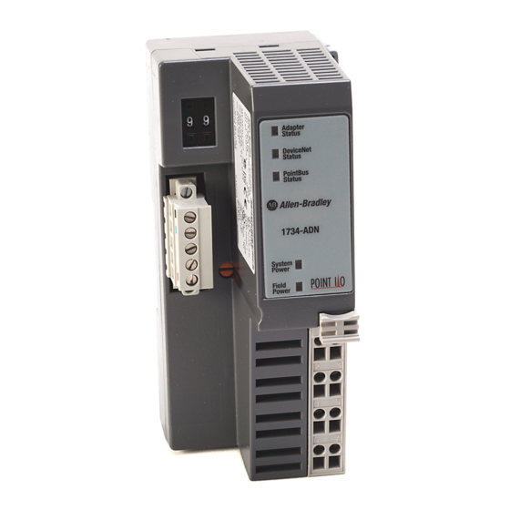
Installing the POINT I/O Adapter or
Communication Interface
The 1734-ADN DeviceNet adapter and
1734-PDN communication interface install
onto a DeviceNet network.
System Power Indicator
DeviceNet
Module Power Indicator
connector
DIN Rail Locking Screw
Module
label
Interlocking
side pieces
1734-PDN Adaptor
1. Position the interface above the DIN rail.
2. Press down firmly to install the interface
on the DIN rail.
3. The locking mechanism will lock the
interface to the DIN rail.
4. Remove safety end cap. Slide it up to
expose backplane and power connections.
Do not discard end cap. Use
ATTENTION
end cap to cover exposed
connections on the last terminal
!
base in the chassis. Failure to
do so could result in injury or
equipment damage.
If installing a replacement interface to an
existing system:
1. Position the interface above the DIN rail.
2. Slide the interface down allowing the
interlocking side pieces to engage the
adjacent module.
3. Press firmly to seat the interface on the
DIN rail. The interface locking mechanism
will snap into place.
4. To remove the interface from the DIN rail,
pull up on the RTB removal handle to
remove the terminal block.
5. Use a small bladed screwdriver to rotate
the DIN rail locking screw to a vertical
position.
6. This releases the locking mechanism.
Then lift straight up to remove.
Installing the Field Potential Dist.
The 1734-FPD looks
IMPORTANT
like the 1734-PDN but
has no indicators.
The 1734-FPD installs onto a DeviceNet
network using the same steps as the
1734-PDN communication interface with one
additional step included.
Bases: 1734-TB, -TBS, -TB3, -TB3S
(RTB usage covered)
After positioning the 1734-FPD above the
DIN rail, engage the interlocking side pieces
with the unit on the left.
Installing the POINT I/O Wiring Base
The wiring base consists of a base and a
removable terminal block (RTB). The
1734-TB uses screw-clamp terminations; the
1734-TBS uses spring-clamp terminations.
(orange)
Mech. Keying
Safety
End Cap
RTB Removal
Handle
Removable
Terminal
Block
Interlocking
Side Pieces
Wiring Base
Installing the Wiring Base
1. Position wiring base vertically above
installed units (interface, power supply or
existing module.
2. Slide the wiring base down allowing the
interlocking side pieces to engage the
adjacent module or interface.
3. Press firmly to seat the wiring base on the
DIN rail. The wiring base will snap into
place.
4. To remove the wiring base from the DIN
rail, remove the module, and use a small
bladed screwdriver to rotate the base
locking screw to a vertical position. This
releases the locking mechanism. Then lift
straight up to remove.
Installing the Removable Terminal Block
A removable terminal block is supplied with
your terminal base. To remove, pull up on
the RTB removal handle.
Do not pull on the installed
ATTENTION
wiring to remove a terminal
block. A shock hazard exists if
!
power is applied to the
terminal block.
This allows the base to be removed and
replaced as necessary without removing any
of the wiring. To reinsert the removable
terminal block:
1. Insert the end opposite the handle into the
base unit. This end has a curved section
that engages the wiring base.
2. Rotate the terminal block into the wiring
base until it locks itself in place.
™
I/O system:
Modules:1734-IA2, IB2, -IB4, -IJ, -IK, -IM2, -IV2, -IV4, -IE2C, -OA2,
-OE2C, -OW2, -OB2E, -OB4E, -VHSC24, -VHSC5
DIN Rail Locking Screw (orange)
RTB
6
Removal
Handle
RTB
Publication 1734-IN510B-EN-P - August 2000
Installation Instructions
3. If an I/O module is installed, snap the RTB
handle into place on the module.
4. Insert module straight down into wiring
base and press to secure. Module locks
into place.
Removing a Wiring Base
To remove a wiring base, you must remove
any installed module, and remove the
removable terminal block (if wired). Then
follow these steps:
1. Remove the RTB (if wired).
2. Turn the wiring base locking screw to a
vertical position to unlock the base from
the DIN rail.
3. Slide base up to release it from its mating
units.
Installing the I/O Module
I/O Module
Module
Locking
Mechanism
Module
Wiring
Diagram
Mech.
Keying
DIN Rail
Locking Screw
(orange)
Wiring Base
The module can be installed before, or after
base installation. Make sure that the wiring
base is correctly keyed before installing the
module into the wiring base. In addition,
make sure the wiring base locking screw is
positioned horizontal according to the base.
1. Using a bladed screwdriver, rotate the
keyswitch on the wiring base clockwise to
until the number required for the type of
module being installed aligns with the
notch in the base.
2. Make certain the DIN rail locking screw is
in the horizontal position. (You cannot
insert the module if the locking
mechanism is unlocked.)
3. Insert the module straight down into the
wiring base and press to secure. The
module will lock into place.
RTB
Removal
Handle
RTB
30880-MB
Advertisement
Table of Contents

Related Manuals for Allen-Bradley POINT I/O 1734-IJ


Summarization of Contents
Installing the POINT I/O Adapter or Communication Interface
1734-PDN Adaptor Installation
Steps for installing the 1734-PDN adapter onto the DIN rail and securing it.
Replacing an Existing Interface
Procedure to remove an existing interface and install a new one.
Installing the Field Potential Distribution (1734-FPD)
Install the 1734-FPD using similar steps to the 1734-PDN.
Installing the POINT I/O Wiring Base
Wiring Base Installation
Steps to position and secure the wiring base onto the DIN rail.
Removable Terminal Block (RTB) Installation
Procedure for inserting and removing the terminal block from the wiring base.
Installing the I/O Module
Module to Wiring Base Installation
Steps to correctly key and install an I/O module into the wiring base.
Wiring Diagrams
1734-ADN Wiring Diagram
Wiring diagram for the 1734-ADN DeviceNet adapter.
1734-PDN Wiring Diagram
Wiring diagram for the 1734-PDN communication interface.
1734-FPD Wiring Diagram
Wiring diagram for the 1734-FPD module.
1734-IA2 Wiring Diagram
Wiring diagram for the 1734-IA2 analog input module.
1734-IB2 Wiring Diagram
Wiring diagram for the 1734-IB2 DC input sink module.
1734-IB4 Wiring Diagram
Wiring diagram for the 1734-IB4 DC input sink module.
1734-IM2 Wiring Diagram
Wiring diagram for the 1734-IM2 analog input module.
1734-IV2 Wiring Diagram
Wiring diagram for the 1734-IV2 DC input source module.
1734-IV4 Wiring Diagram
Wiring diagram for the 1734-IV4 DC input source module.
1734-0A2 Wiring Diagram
Wiring diagram for the 1734-0A2 DC output module.
More Wiring Diagrams
1734-0B2E Wiring Diagram
Wiring diagram for the 1734-0B2E DC output module.
1734-0B4E Wiring Diagram
Wiring diagram for the 1734-0B4E DC output module.
1734-IE2C Wiring Diagram
Wiring diagram for the 1734-IE2C analog input module.
1734-0E2C Wiring Diagram
Wiring diagram for the 1734-0E2C analog output module.
1734-0W2 Wiring Diagram
Wiring diagram for the 1734-0W2 relay output module.
1734-IJ & IK Wiring Diagram
Wiring diagram for 1734-IJ and 1734-IK counter modules.
1734-VHSC24 & VHSC5 Wiring Diagram
Wiring diagrams for 1734-VHSC24 and 1734-VHSC5 modules.
General Specifications
Environmental Conditions
Operating temperature, storage temperature, and humidity specifications.
Shock and Vibration Resistance
Specifications for shock and vibration resistance.
Wire Size and Certifications
Conductor wire size, category, and agency certifications.
Terminal Base Specifications
1734-TB, -TBS, -TB3 and -TB3S Specifications
Specifications for terminal bases including voltage, current, dimensions, and mass.
1734-ADN Adapter Specifications
Expansion Capacity and Communication Rate
I/O expansion capacity and DeviceNet communication rates.
Module Location and Power Supply
Module location and power supply requirements for the adapter.
DeviceNet Voltage and Power Requirements
DeviceNet input voltage range and power consumption details.
DeviceNet Cable and Wiring Terminations
DeviceNet cable type and field wiring terminations.
Overvoltage Protection and Indicators
Overvoltage protection and status indicators for the adapter.
Isolation Voltage and Thermal Dissipation
Isolation voltage and thermal dissipation specifications.
Dimensions and Mass
Physical dimensions and mass of the adapter.
Power Supply Specifications
Details on input voltage, inrush current, and protection for the power supply.
1734-PDN Interface Specifications
Expansion Capacity and Communication Rate
I/O expansion capacity and DeviceNet communication rates.
DeviceNet Power Requirements
DeviceNet power requirements including voltage and current.
Module Location and Indicators
Module location and status indicators for the interface.
DeviceNet Cable and Dimensions
DeviceNet cable type and physical dimensions of the interface.
Overvoltage Protection and Field Power
Overvoltage protection and field power bus specifications.
Field Wiring Terminations and Power Dissipation
Field wiring terminations and power dissipation.
Power Supply Specifications
Power supply input voltage, current, and interruption handling.
1734-FPD Specifications
Pointbus Output Current and Indicators
Pointbus output current and indicators for the FPD module.
Input Current and Module Location
Input current and module location details for the FPD.
Field Power Bus Voltage and Current
Field power bus voltage and current specifications for the FPD.
Input Voltage Rating and Dimensions
Input voltage rating and physical dimensions of the FPD.
Power Supply and Mass
Power supply requirements and mass of the FPD.
1734-AC Input Modules Specifications
Module Location and Pointbus Current
Module location and pointbus current for AC input modules.
Power Dissipation and Thermal Dissipation
Power and thermal dissipation for AC input modules.
Isolation Voltage and Dimensions
Isolation voltage and physical dimensions of AC input modules.
External AC Power Supply Voltage and Range
External AC power supply voltage and range for AC input modules.
Field Wiring Terminations and Mass
Field wiring terminations and mass for AC input modules.
Input Specifications (IA2, IM2)
Number of inputs, ON/OFF state voltage, and current for AC input modules.
OFF-State Voltage and Current
OFF-state voltage and current specifications for AC input modules.
Delay Time and Keyswitch Position
Input delay time and keyswitch position for AC input modules.
1734-AC Output Module Specifications
Module Location and Pointbus Current
Module location and pointbus current for the 0A2 output module.
Power Dissipation and Isolation Voltage
Power dissipation and isolation voltage for the 0A2 output module.
External AC Power Supply Voltage and Dimensions
External AC power supply voltage and dimensions for the 0A2 output module.
Field Wiring Terminations and Mass
Field wiring terminations and mass for the 0A2 output module.
Output Specifications (0A2)
Number of outputs, ON/OFF state voltage, and current for the 0A2 module.
ON-State Voltage Drop and Surge Current
ON-state voltage drop and surge current for the 0A2 output module.
Output Current Rating and Delay Time
Output current rating and delay time for the 0A2 output module.
Keyswitch Position and Indicators
Keyswitch position and indicators for the 0A2 output module.
DC Input Sink Modules Specifications
Module Location and Pointbus Current
Module location and pointbus current for DC input sink modules.
Inputs/Module and Input Filter Time
Number of inputs and input filter time for DC input sink modules.
ON-State Voltage and Current
ON-state voltage and current specifications for DC input sink modules.
OFF-State Voltage and Current
OFF-state voltage and current specifications for DC input sink modules.
Input Impedance and Keyswitch Position
Input impedance and keyswitch position for DC input sink modules.
Power Dissipation and Power Supply
Power dissipation and power supply for DC input sink modules.
Field Power Supply Voltage and Thermal Dissipation
Field power supply voltage and thermal dissipation for DC input sink modules.
Dimensions and Isolation Voltage
Dimensions and isolation voltage for DC input sink modules.
Mass
Mass of the DC input sink modules.
DC Input Source Modules Specifications
Module Location and Pointbus Current
Module location and pointbus current for DC input source modules.
Inputs/Module and Input Filter Time
Number of inputs and input filter time for DC input source modules.
ON-State Voltage and Current
ON-state voltage and current for DC input source modules.
OFF-State Voltage and Current
OFF-state voltage and current for DC input source modules.
Input Impedance and Keyswitch Position
Input impedance and keyswitch position for DC input source modules.
Power Dissipation and Power Supply
Power dissipation and power supply for DC input source modules.
Field Power Supply Voltage and Thermal Dissipation
Field power supply voltage and thermal dissipation for DC input source modules.
Dimensions and Mass
Dimensions and mass for DC input source modules.
DC Electronically Protected Output Modules Specifications
Module Location and Pointbus Current
Module location and pointbus current for protected output modules.
Number of Outputs and Keyswitch Position
Number of outputs and keyswitch position for protected output modules.
ON-State Current and Output Signal Delay
ON-state current and output signal delay for protected output modules.
OFF-State Voltage and OFF-State Leakage
OFF-state voltage and leakage current for protected output modules.
ON-State Voltage Drop and Power Supply
ON-state voltage drop and power supply for protected output modules.
Output Current Rating and Voltage Range
Output current rating and voltage range for protected output modules.
Surge Current and Indicators
Surge current and indicator status for protected output modules.
Power Dissipation and Mass
Power dissipation and mass for protected output modules.
Analog Modules Specifications
1734-IE2C and 1734-0E2C Module Location
Module location for IE2C and OE2C analog modules.
Inputs/Module and Pointbus Current
Inputs per module and pointbus current for analog modules.
Input Current and Number of Outputs
Input current and number of outputs for analog modules.
Output Current Terminal and Keyswitch Position
Output current terminal and keyswitch position for analog modules.
Data Format and Resolution Current
Data format and resolution current for analog modules.
Conversion Type and Calibration
Conversion type and calibration status for analog modules.
Conversion Rate and Common Mode Rejection Ratio
Conversion rate and common mode rejection ratio for analog modules.
External DC Power Supply Voltage and Step Response
External DC power supply voltage and step response for analog modules.
Supply Current and Notch Filter Settings
Supply current and notch filter settings for analog modules.
Field Wiring Terminations and Normal Mode Rejection Ratio
Field wiring terminations and normal mode rejection ratio for analog modules.
Absolute Accuracy and Resistance Load
Absolute accuracy and resistance load on mA output for analog modules.
Maximum Overload and Mass
Maximum overload protection and mass for analog modules.
Indicators and Normal Dissipation
Indicators and normal dissipation for analog modules.
Power Dissipation and Thermal Dissipation
Power dissipation and thermal dissipation for analog modules.
Relay Module Specifications
1734 Relay Module Location
Module location for the 1734 Relay Module.
Number of Outputs and Pointbus Current
Number of outputs and pointbus current for the relay module.
OFF-State Leakage and Keyswitch Position
OFF-state leakage and keyswitch position for the relay module.
Output Voltage Range and Output Signal Delay
Output voltage range and output signal delay for the relay module.
Power Supply and Power Rating
Power supply and power rating for the relay module.
Output Current Rating and Thermal Dissipation
Output current rating and thermal dissipation for the relay module.
Counter Module Specifications
1734 Counter Modules (IJ, IK) Specifications
Specifications for 1734-IJ and 1734-IK counter modules.
Number of Inputs and Field Power Supply Voltage
Number of inputs and field power supply voltage for counter modules.
Input Current and Voltage Range
Input current and voltage range for counter modules.
Input OFF-State Current and Supply Current
Input OFF-state current and supply current for counter modules.
Input OFF-State Voltage and Operate/Release Time
Input OFF-state voltage and operate/release time for counter modules.
Input Filter Selections and Bounce Time
Input filter selections and bounce time for counter modules.
Module Location and Mass
Module location and mass for counter modules.
Keyswitch Position and Indicators
Keyswitch position and indicators for counter modules.
Thermal Dissipation and Pointbus Current
Thermal dissipation and pointbus current for counter modules.
Power Dissipation and Mass
Power dissipation and mass for counter modules.
Isolation Voltage and Field Wiring Terminations
Isolation voltage and field wiring terminations for counter modules.
Dimensions (Inches/Millimeters)
Physical dimensions in inches and millimeters for counter modules.
High Speed Counter Modules Specifications
1734-VHSC24, -VHSC5 Module Location
Module location for VHSC24 and VHSC5 high speed counter modules.
Pointbus Current and Keyswitch Position
Pointbus current and keyswitch position for high speed counter modules.
Power Dissipation and Field Power Bus
Power dissipation and field power bus specifications for high speed counter modules.
Thermal Dissipation and Field Wiring Terminations
Thermal dissipation and field wiring terminations for high speed counter modules.
Isolation Voltage and Dimensions
Isolation voltage and dimensions for high speed counter modules.
High Speed Counter Modules Specifications (Continued)
Mass
Mass of the high speed counter modules.
Input Specifications
Number of inputs, voltage, current, and frequency for high speed counter modules.
Maximum Input Frequency
Maximum input frequency for high speed counter modules.
Maximum ON-State Voltage
Maximum ON-state voltage for high speed counter modules.
Input Filter Selections
Input filter selections for high speed counter modules.
Input OFF-State Current and Voltage
Input OFF-state current and voltage for high speed counter modules.
Input ON-State Current and Voltage
Input ON-state current and voltage for high speed counter modules.
Output Specifications (VHSC24, VHSC4)
Output specifications including number of outputs and voltage range.
Output Control and ON-State Current
Output control and ON-state current for high speed counter modules.
Output Supply Voltage Range and Open Wire Detection
Output supply voltage range and open wire detection for high speed counter modules.
OFF-State Leakage Current and ON-State Voltage Drop
OFF-state leakage current and ON-state voltage drop for high speed counter modules.
Short Circuit Current and Delay Time
Short circuit current and delay time for high speed counter modules.
European Communities Directive Compliance
EMC Directive Compliance
Compliance with EMC Directive 89/336/EC and relevant standards.
Low Voltage Directive Compliance
Compliance with Low Voltage Directive 73/23/EEC and EN 61131-2.
Need help?
Do you have a question about the POINT I/O 1734-IJ and is the answer not in the manual?
Questions and answers