Advertisement
POINT I/O
Use this document to install and wire the following components of your POINT
Interface: 1734-ADN, -PDN
POINT I/O modules have no switches to set. You set module parameters with a software configuration tool. To obtain EDS files for use in
configuration, go to: http://www.ab.com/networks/eds
This product installation information is also available at: http://www.ab.com/manuals/io/
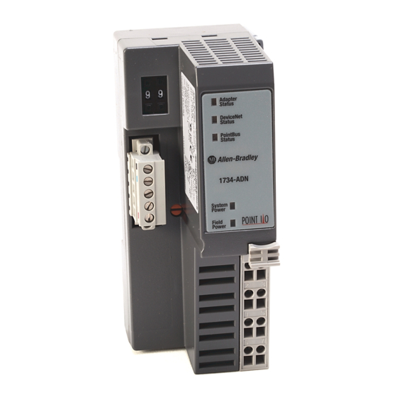
Installing the POINT I/O Adapter or
Communication Interface
The 1734-ADN DeviceNet adapter and
1734-PDN communication interface install
onto a DeviceNet network.
System Power Indicator
DeviceNet
Module Power Indicator
connector
DIN Rail Locking Screw
Module
label
Interlocking
side pieces
1734-PDN Adaptor
1. Position the interface above the DIN rail.
2. Press down firmly to install the interface
on the DIN rail.
3. The locking mechanism will lock the
interface to the DIN rail.
4. Remove safety end cap. Slide it up to
expose backplane and power connections.
Do not discard end cap. Use
ATTENTION
end cap to cover exposed
connections on the last terminal
!
base in the chassis. Failure to
do so could result in injury or
equipment damage.
If installing a replacement interface to an
existing system:
1. Position the interface above the DIN rail.
2. Slide the interface down allowing the
interlocking side pieces to engage the
adjacent module.
3. Press firmly to seat the interface on the
DIN rail. The interface locking mechanism
will snap into place.
4. To remove the interface from the DIN rail,
pull up on the RTB removal handle to
remove the terminal block.
5. Use a small bladed screwdriver to rotate
the DIN rail locking screw to a vertical
position.
6. This releases the locking mechanism.
Then lift straight up to remove.
Installing the Field Potential Dist.
The 1734-FPD looks
IMPORTANT
like the 1734-PDN but
has no indicators.
The 1734-FPD installs onto a DeviceNet
network using the same steps as the
1734-PDN communication interface with one
additional step included.
Bases: 1734-TB, -TBS, -TB3, -TB3S
(RTB usage covered)
After positioning the 1734-FPD above the
DIN rail, engage the interlocking side pieces
with the unit on the left.
Installing the POINT I/O Wiring Base
The wiring base consists of a base and a
removable terminal block (RTB). The
1734-TB uses screw-clamp terminations; the
1734-TBS uses spring-clamp terminations.
(orange)
Mech. Keying
Safety
End Cap
RTB Removal
Handle
Removable
Terminal
Block
Interlocking
Side Pieces
Wiring Base
Installing the Wiring Base
1. Position wiring base vertically above
installed units (interface, power supply or
existing module.
2. Slide the wiring base down allowing the
interlocking side pieces to engage the
adjacent module or interface.
3. Press firmly to seat the wiring base on the
DIN rail. The wiring base will snap into
place.
4. To remove the wiring base from the DIN
rail, remove the module, and use a small
bladed screwdriver to rotate the base
locking screw to a vertical position. This
releases the locking mechanism. Then lift
straight up to remove.
Installing the Removable Terminal Block
A removable terminal block is supplied with
your terminal base. To remove, pull up on
the RTB removal handle.
Do not pull on the installed
ATTENTION
wiring to remove a terminal
block. A shock hazard exists if
!
power is applied to the
terminal block.
This allows the base to be removed and
replaced as necessary without removing any
of the wiring. To reinsert the removable
terminal block:
1. Insert the end opposite the handle into the
base unit. This end has a curved section
that engages the wiring base.
2. Rotate the terminal block into the wiring
base until it locks itself in place.
™
I/O system:
Modules:1734-IA2, IB2, -IB4, -IJ, -IK, -IM2, -IV2, -IV4, -IE2C, -OA2,
-OE2C, -OW2, -OB2E, -OB4E, -VHSC24, -VHSC5
DIN Rail Locking Screw (orange)
RTB
6
Removal
Handle
RTB
Publication 1734-IN510B-EN-P - August 2000
Installation Instructions
3. If an I/O module is installed, snap the RTB
handle into place on the module.
4. Insert module straight down into wiring
base and press to secure. Module locks
into place.
Removing a Wiring Base
To remove a wiring base, you must remove
any installed module, and remove the
removable terminal block (if wired). Then
follow these steps:
1. Remove the RTB (if wired).
2. Turn the wiring base locking screw to a
vertical position to unlock the base from
the DIN rail.
3. Slide base up to release it from its mating
units.
Installing the I/O Module
I/O Module
Module
Locking
Mechanism
Module
Wiring
Diagram
Mech.
Keying
DIN Rail
Locking Screw
(orange)
Wiring Base
The module can be installed before, or after
base installation. Make sure that the wiring
base is correctly keyed before installing the
module into the wiring base. In addition,
make sure the wiring base locking screw is
positioned horizontal according to the base.
1. Using a bladed screwdriver, rotate the
keyswitch on the wiring base clockwise to
until the number required for the type of
module being installed aligns with the
notch in the base.
2. Make certain the DIN rail locking screw is
in the horizontal position. (You cannot
insert the module if the locking
mechanism is unlocked.)
3. Insert the module straight down into the
wiring base and press to secure. The
module will lock into place.
RTB
Removal
Handle
RTB
30880-MB
Advertisement
Table of Contents

Related Manuals for Allen-Bradley POINT I/O 1734-IK


Summary of Contents for Allen-Bradley POINT I/O 1734-IK
- Page 1 Installation Instructions POINT I/O ™ Use this document to install and wire the following components of your POINT I/O system: Interface: 1734-ADN, -PDN Bases: 1734-TB, -TBS, -TB3, -TB3S Modules:1734-IA2, IB2, -IB4, -IJ, -IK, -IM2, -IV2, -IV4, -IE2C, -OA2, (RTB usage covered) -OE2C, -OW2, -OB2E, -OB4E, -VHSC24, -VHSC5 POINT I/O modules have no switches to set.
-
Page 2: Wiring Diagrams
POINT I/O Wiring Diagrams 1734-ADN 1734-PDN Black Black Blue CAN - Low Blue CAN - Low Chass Chass Chass Chass 12/24V dc DeviceNet 12/24V dc DeviceNet connection Power connection Power Bare Shield Bare Shield White CAN - High White CAN - High V dc V dc Daisy chain... -
Page 3: Specifications
POINT I/O Wiring Diagrams 1734-OB2E 1734-OB4E 1734-IE2C In 0 In 1 Chass Chass Load Load Load Load Load Load 42014 42017 42015 V = 12/24V dc, C = Common V = 12/24V dc, C = Common V = 12/24V dc, C = Common Chass GND = Chassis Ground Field power is supplied from power bus Field power is supplied from power bus This supply will be connected to the internal power bus. -
Page 4: Specification
Reverse polarity protected with 1734-EP24DC) Protection DeviceNet Communication 125K bit/s (500m maximum) DeviceNet Cable Allen-Bradley part number 1485C-P1-Cxxx Rate 250K bit/s (250m maximum) Refer to publication DN-2.5 for more information 500K bit/s (100m maximum) Module Location Starter module - left side of 1734 system... - Page 5 POINT I/O Specification Value: Specification Value: Inrush Current 6A for 5ms Power Consumption 7.0W max @ 25V dc Pointbus Output Current 1A maximum @ 5V dc +5% (4.75-5.25) Mass 4.56 oz/129.28 grams Isolation Voltage 1528V rms/V ac 1734-FPD Specifications Specification Value: Specification Value:...
- Page 6 POINT I/O 1734-AC Output Modules (1734-OA2) Specification Value Specification Value Module Location 1734-TB, TBS, TB3 or -TB3S wiring base assembly Pointbus Current 75mA maximum @ 5V dc Power Dissipation 0.8W maximum @ 28.8V dc Thermal Dissipation 2.7 BTU/hr maximum @ 28.8V dc Isolation Voltage Tested at 1500V rms/V ac dc for 1s Mass...
- Page 7 POINT I/O 1734 DC Input Source Modules (1734-IV2, -IV4,) Specification: Value: Specification: Value: Module Location 1734-TB or -TBS terminal base unit Pointbus Current 75mA max @ 5V dc Inputs/Module 2 (1 group of 2) non-isolated, sourcing (1734-IV2) OFF to ON: 0-65ms (1ms default) Input Filter Time 4 (1 group of 4) non-isolated, sourcing (1734-IV4) ON to OFF: 0-65ms (1ms default)
- Page 8 POINT I/O 1734 Analog Modules (1734-IE2C, -OE2C) Specification: 1734-IE2C Value: 1734-OE2C Value: Specification: 1734-IE2C Value: 1734-OE2C Value: Module Location 1734-TB or -TBS terminal base unit Pointbus Current 75mA max @ 5V dc Inputs/Module 2 single-ended, Number of Outputs 2 single-ended, non-isolated non-isolated Input Current Terminal...
- Page 9 POINT I/O Specification: Value: Specification: Value: Isolation Voltage Field Power Between any 2 sets 2550V dc for 1s Supply Voltage None required of contacts Voltage Range 240V ac max Customer load to logic 2550V dc for 1s Supply Current 2A/channel max 4A/module Initial Contact Resistance 30mΩ...
-
Page 10: Input Specifications
POINT I/O Mass 1.15 oz/32.60 grams Input Specifications Number of Inputs 1 - 1 group of A/Areturn, B/Breturn and Z/Zreturn Maximum Input Frequency 1.0MHz counter and encoder X1 configurations 500kHz encoder X2 configuration (no filter) 250kHz encoder X4 configuration (no filter) Input Voltage 15-24V dc(1734-VHSC24) Maximum ON-State... -
Page 11: European Communities (Ec) Directive Compliance
Programmable Controllers, Part 2 - Equipment Requirements and Tests. For specific information required by EN 61131-2, see the appropriate sections in this publication, as well as the Allen-Bradley publication Industrial Automation Wiring and Grounding Guidelines For Noise Immunity, publication 1770-4.1. - Page 12 POINT I/O Publication 1734-IN510B-EN-P - August 2000 PN 957395-13 Supersedes Publication 1734-5.10 - September 1999 © 2000 Rockwell International Corporation. Printed in the U.S.A.
Need help?
Do you have a question about the POINT I/O 1734-IK and is the answer not in the manual?
Questions and answers