Sign In
Upload
Download
Table of Contents
Contents
Add to my manuals
Delete from my manuals
Share
URL of this page:
HTML Link:
Bookmark this page
Add
Manual will be automatically added to "My Manuals"
Print this page
×
Bookmark added
×
Added to my manuals
Manuals
Brands
Fluke Manuals
Test Equipment
2635A
User manual
Fluke 2635A User Manual
Data bucket
Hide thumbs
1
2
Table Of Contents
3
4
5
6
7
8
9
10
11
12
13
14
15
16
17
18
19
20
21
22
23
24
25
26
27
28
29
30
31
32
33
34
35
36
37
38
39
40
41
42
43
44
45
46
47
48
49
50
51
52
53
54
55
56
57
58
59
60
61
62
63
64
65
66
67
68
69
70
71
72
73
74
75
76
77
78
79
80
81
82
83
84
85
86
87
88
89
90
91
92
93
94
95
96
97
98
99
100
101
102
103
104
105
106
107
108
109
110
111
112
113
114
115
116
117
118
119
120
121
122
123
124
125
126
127
128
129
130
131
132
133
134
135
136
137
138
139
140
141
142
143
144
145
146
147
148
149
150
151
152
153
154
155
156
157
158
159
160
161
162
163
164
165
166
167
168
169
170
171
172
173
174
175
176
177
178
179
180
181
182
183
184
185
186
187
188
189
190
191
192
193
194
195
196
197
198
199
200
201
202
203
204
205
206
207
208
209
210
211
212
213
214
215
216
217
218
219
220
221
222
223
224
225
226
227
228
229
230
231
232
233
234
235
236
237
238
239
240
241
242
243
244
245
246
247
248
249
250
251
252
253
254
255
256
257
258
259
260
261
262
263
264
265
266
267
268
page
of
268
Go
/
268
Contents
Table of Contents
Bookmarks
Table of Contents
Table of Contents
Preparation for Use
Introduction
Operating Modes
Chapter 1
Front Panel Operation
Memory Card Operation
Computer Operation
Printer Operation
Modem Operation
Measurement Capabilities
MX+B Scaling
Alarms
Totalizer Channel
Alarm Outputs and Digital I/O
Applications Software
Hydra Starter Package
Hydra Logger
Options and Accessories
Memory Card Reader
Connector Set, 2620A-100
Setting up the Instrument
Unpacking and Inspecting the Instrument
Adjusting the Handle
Connecting the Instrument to a Power Source
AC Operation
DC Operation
Input Channels
Measurement Connections
Using Shielded Wiring
Crosstalk
Universal Input Module Connections
Alarm Outputs Connections
DC Power
Alarm Outputs
External Trigger Input
Digital I/O Connections
Digital I/O
Totalizer Input
Controls and Indicators
Front Panel Controls
Front Panel Indicators
Front Panel Operations
Summary of Front Panel Operations
Configuring the Instrument for Operation
Chapter 2
Turning the Power on
Selecting a Channel
Configuring a Measurement Channel
Configuring a Channel to Measure DC Volts
Configuring a Channel to Measure AC Volts
Configuring a Channel to Measure Resistance
Configuring a Channel to Measure Frequency
Configuring a Channel to Measure Temperature
Thermocouples
Resistance-Temperature Detectors
Thermocouple Restrictions
Resistance Temperature Detectors Restrictions
Configuring a Channel off
Setting Operating Conditions
Setting the Scan Interval
Setting the Measurement Rate
Setting the Alarms
Alarm Indications While Scanning
Alarm Indications While Monitoring
Alarm Indications While Reviewing
Clearing Alarm Parameters from a Channel
Alarm Outputs for Channel 0 to 3 Using the Alarm Outputs Connector
Alarm Outputs for Channels 4 to 20 Using the Digital I/O Connector
Alarms and Autoprinting
Alarms and Monitor-Alarm Triggering
Alarms and MX+B Scaling
Setting the MX+B Scaling
Examples
Restrictions
Clearing MX+B Scaling from a Channel
Operating Modes
Using the Scan Mode
Memory Card as a Data Destination
Memory Card Formatting
Memory Card Capacity
Memory Card Files
Memory Card Exchange During Scanning
Memory Card Data Extraction
Memory Card Error Messages
Using the Monitor Mode
Using the Review Mode
Additional Features
Scan Triggering Options
External Trigger
Monitor-Alarm Trigger
Triggering Options and Memory Card Operation
Totalizer Operation
Digital Input/Output Lines
Setting Date and Time
Reading Instrument Software Versions
Returning to the Local Mode
Front Panel Key Lockout Options
Instrument Interfaces
Memory Card Interface
RS-232 Computer Interface
Using the RS-232 Computer Interface with a Printer
Using the RS-232 Computer Interface with a Modem
Memory Card Operations
Summary of Memory Card Operations
Chapter 3
Memory Card Files
Setup Files
Data Files
Memory Card Capacity
Memory Card Battery
Inserting and Removing the Memory Card
Inserting a Memory Card
Removing a Memory Card
Changing the Memory Card During Scanning
Setting the Memory Card Write-Protect Feature
Installing or Replacing the Memory Card Battery
Initializing a Memory Card
Recording Measurement Results During Scanning
Setup File Procedures
Using Setup Store
Using Setup Load
Using Setup Erase
Data File Procedures
Using Data Open
Using Data Erase
Setup and Data Files Directory
Setup and Data File Current Status
Memory Card File Operations to and from a PC
Computer Operations
Chapter 4
Summary of Computer Operations
Connecting the Instrument to a PC
Configuring the Instrument for Computer Operations
Configuring the PC for Computer Operations
Testing the Instrument/Pc RS-232 Interface
Testing the RS-232 Interface Using Terminal Emulation (Windows)
Testing the RS-232 Interface Using Terminal Emulation (Generic)
Testing the RS-232 Interface Using Gwbasic
Testing the RS-232 Interface Using Qbasic
Computer Interface Commands and Operation
How the Instrument Processes Input
Input Terminators
Input String Examples
Sending Numeric Values to the Instrument
How the Instrument Processes Output
Status Registers
Instrument Event Register (IER)
Standard Event Status Register (ESR)
Status Byte Register (STB)
Computer Interface Command Set
Xmodem File Transfers
Printer Operations
Chapter 5
Summary of Printer Operations
Connecting the Instrument to a Printer
Configuring for Printer Operations
Printing Measurement Data and Memory Card Directory
Problems
Printing Measurement Results During Scanning
Printing the Review Array
Printing the Directory of the Memory Card
Modem Operations
Chapter 6
Summary of Modem Operations
Connecting the Modem to a PC for Modem Configuration
Configuring the Instrument Modem for Modem Operations
Connecting the Modem to an Instrument
Configuring the Instrument for Modem Operations
Testing the RS-232/Modem Interface
Maintenance
Chapter 7
Introduction
Cleaning
Line Fuse
Selftest Diagnostics and Error Codes
Performance Tests
Accuracy Verification Test
Channel Integrity Test
Thermocouple Measurement Range Accuracy Test
Four-Terminal Resistance Test
Thermocouple Temperature Accuracy Test
Open Thermocouple Response Test
RTD Temperature Accuracy Test
RTD Temperature Accuracy Test (Using Decade Resistance Source)
RTD Temperature Accuracy Test (Using DIN/IEC 751 RTD)
Digital Input/Output Verification Tests
Digital Output Test
Digital Input Test
Totalizer Test
Totalizer Sensitivity Test
Dedicated Alarm Output Test
External Trigger Input Test
Calibration
Variations in the Display
Service
Appendices
A Specifications
Appendix
Specifications
B Crosstalk Considerations
Crosstalk Considerations
C Binary Upload of Logged Data
Binary Upload of Logged Data
RS-232 Cabling
8-Bit Binary-Coded-Decimal Table
E 8-Bit Binary-Coded-Decimal Table
Memory Card File Formats
G True RMS Measurements
True RMS Measurements
Advertisement
Quick Links
1
Front Panel Operation
2
Configuring a Channel to Measure Temperature
Download this manual
®
2635A
Hydra Series II Data Bucket
Users Manual
PN 686698
November 1997
© 1997 Fluke Corporation, All rights reserved. Printed in U.S.A.
All product names are trademarks of their respective companies.
Table of
Contents
Previous
Page
Next
Page
1
2
3
4
5
Advertisement
Table of Contents
Need help?
Do you have a question about the 2635A and is the answer not in the manual?
Ask a question
Questions and answers
Related Manuals for Fluke 2635A
Test Equipment Fluke NetDAQ 2640A User Manual
Networked data acquisition unit (353 pages)
Test Equipment Fluke 190-104 Technical Data Manual
Fluke 190-series ii 4-channel scopemeters product datasheet (9 pages)
Test Equipment Fluke 190-104 Datasheet
Fluke scopemeter family datasheet - 120, 190, 190 series ii (10 pages)
Test Equipment Fluke ScopeMeter 192B Security Procedures
Fluke 190b and 190c series scopemeter - security procedures (2 pages)
Test Equipment Fluke 2AC VoltAlert Technical Data
Non-contact voltage tester (2 pages)
Test Equipment Fluke VoltAlert 2AC Instruction Sheet
(2 pages)
Test Equipment Fluke MicroScanner 2 User Manual
Cable verifier (60 pages)
Test Equipment Fluke 2700G Calibration Manual
Reference pressure gauge (18 pages)
Test Equipment Fluke ScopeMeter 190M-2-III Service Manual
(70 pages)
Test Equipment Fluke 2000ACC Instructions
Accessory kit (4 pages)
Test Equipment Fluke FLUKE-718 User Manual
Pressure calibrator (36 pages)
Test Equipment Fluke CableIQ User Manual
Qualification tester (93 pages)
Test Equipment Fluke 726 User Manual
Multifunction process calibrator (80 pages)
Test Equipment Fluke 6100B User Manual
Electrical power standards (218 pages)
Test Equipment Fluke 6270A Operator's Manual
Pressure controller/calibrator (84 pages)
Test Equipment Fluke 5520A Programmer's Manual
Multi-product calibrator (46 pages)
Summarization of Contents
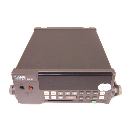
Chapter 1 Preparation for Use
Introduction
Provides an overview of the 2635A Hydra Series II Data Bucket and its capabilities.
Operating Modes
Outlines the five primary modes of operation for the Data Bucket.
Front Panel Operation
Details how to configure channels and perform basic multimeter operations using the front panel.
Memory Card Operation
Explains how to use the memory card for saving setup and recording data.
Measurement Capabilities
Details the electrical and physical parameters the Data Bucket can measure.
Setting Up the Instrument
Covers unpacking, inspecting, and connecting the instrument for initial use.
Chapter 2 Front Panel Operations
Summary of Front Panel Operations
Provides a procedural overview of front panel operations and control diagrams.
Configuring the Instrument for Operation
Details how to power on the instrument and select basic operational settings.
Configuring a Measurement Channel
Guides users through setting up channels for various measurement types.
Setting Operating Conditions
Explains how to set scan interval, measurement rate, alarms, and Mx+B scaling.
Operating Modes
Describes how to use the Scan, Monitor, and Review modes of operation.
Chapter 3 Memory Card Operations
Summary of Memory Card Operations
Introduces memory card usage for saving setup and recording data.
Inserting and Removing the Memory Card
Provides instructions on handling the memory card, including changing it during scanning.
Setup File Procedures
Explains how to store, load, and erase instrument configuration (setup) files.
Data File Procedures
Details how to open and erase measurement data files on the memory card.
Chapter 4 Computer Operations
Summary of Computer Operations
Overviews PC control, configuration, and data exchange with the instrument.
Connecting the Instrument to a PC
Illustrates common configurations for connecting the instrument to a PC via RS-232.
Configuring the Instrument for Computer Operations
Guides setting RS-232 parameters like baud rate, parity, CTS, and echo.
Testing the Instrument/PC RS-232 Interface
Provides procedures for testing the RS-232 link using terminal emulation and BASIC.
Computer Interface Commands and Operation
Explains how the instrument processes commands and outputs data via the computer interface.
Chapter 5 Printer Operations
Summary of Printer Operations
Outlines using an RS-232 connection to print measurement results and memory card directories.
Connecting the Instrument to a Printer
Shows common configurations for connecting the instrument to a printer.
Configuring for Printer Operations
Guides setting RS-232 parameters (baud rate, parity, CTS) for printer communication.
Printing Measurement Data and Memory Card Directory
Describes printing measurement results, review array, and memory card directory.
Chapter 6 Modem Operations
Summary of Modem Operations
Explains modem operations via RS-232 and telephone lines for remote applications.
Connecting the Modem to a PC for Configuration
Details connecting a modem to a PC for configuration using terminal emulation.
Configuring the Instrument for Modem Operations
Guides setting RS-232/modem link parameters like baud rate, parity, CTS, and echo.
Chapter 7 Maintenance
Introduction
Describes basic maintenance tasks the user can perform.
Selftest Diagnostics and Error Codes
Details the selftest routine and lists power-up error codes and their meanings.
Performance Tests
Outlines procedures for verifying instrument performance and accuracy.
RTD Temperature Accuracy Test
Guides testing RTD temperature accuracy using resistance sources or RTDs.
Digital Input/Output Verification Tests
Covers verification tests for digital output and digital input lines.
Calibration
Refers to the service manual for calibration procedures and conditions.
Appendix A Specifications
DC Voltage Measurements
Provides resolution and accuracy specifications for DC voltage measurements.
AC Voltage Inputs
Details resolution, accuracy, and impedance for AC voltage measurements.
Temperature Measurements (Thermocouples)
Lists accuracy specifications for various thermocouple types.
RS-232-C
Specifies RS-232 connector type, signals, baud rates, data format, flow control, and echo.
Appendix B Crosstalk Considerations
Introduction
Augments discussion of AC signal effects on other channels, providing references for analysis.
AC Signal Cross Talk in a DC Voltage Channel
Quantifies AC signal crosstalk effects on DC voltage measurement channels.
AC Signal Cross Talk into an AC Voltage Channel
Details AC signal crosstalk effects on AC voltage measurement channels.
Appendix C Binary Upload of Logged Data
Introduction
Introduces the LOG_BIN? query for uploading logged data and its conversion process.
Decoding the ASCII String
Explains how to decode the ASCII string response into binary data.
Appendix D RS-232 Cabling
Introduction
Details RS-232 cabling for connecting instruments to PCs, printers, or modems.
Connections
Summarizes cable requirements and typical connection diagrams for RS-232.
Appendix F Memory Card File Formats
Introduction
Describes the format of binary files created by the 2635A Data Bucket for scan data.
Data File Format
Details the two-part format of data files (header and scan data).
Setup File Format
Explains the format of setup files used for instrument configurations.
Appendix G True RMS Measurements
Introduction
Explains how the instrument measures true RMS values of AC voltages.
Waveform Comparison (True RMS VS Average Responding)
Compares true RMS measurements with average-responding devices for common waveforms.
Table of Contents
Save PDF
Print
Rename the bookmark
Delete bookmark?
Delete from my manuals?
Login
Sign In
OR
Sign in with Facebook
Sign in with Google
Upload manual
Upload from disk
Upload from URL
Need help?
Do you have a question about the 2635A and is the answer not in the manual?
Questions and answers