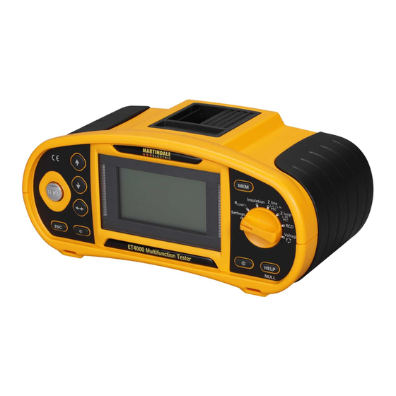
Table of Contents
Advertisement
Advertisement
Table of Contents

Summarization of Contents
Safety Information
Meaning of Symbols and Markings
Explains the various symbols and markings used throughout the manual for safety and operation.
Precautions
Details essential warnings and cautions to ensure safe use of the instrument and prevent hazards.
Introduction
Inspection
Guide on how to inspect the instrument and accessories for any signs of damage upon receipt.
Description
An overview of the Martindale ET4000/ET4500 as multifunction installation testers and their capabilities.
Accessories
Lists all supplied and optional accessories for the ET4000 and ET4500 models.
Instrument Description
Front Panel
Detailed explanation of the instrument's front panel layout, controls, and display elements.
Connector Panel
Identifies and describes the various input/output terminals and connectors on the instrument.
Instrument Rear
Information on the instrument's rear panel, including battery and fuse compartment access.
Carrying the Instrument
Instructions and examples for attaching and using the carrying strap for portability.
Instrument Operation
Batteries and Charging
Guidance on battery types, installation, charging procedure, and related safety warnings.
Display and Audible Indication
Explains how to interpret instrument readings, battery status, and audible alerts.
Function Selection
Describes how to navigate through measurement functions and settings using the selector switch and keys.
Settings
Details how to configure instrument options such as date, time, RCD standards, and Z factor.
Use of Test Leads and Probes
Instructions on correctly connecting and using various test leads, probes, and accessories.
Measurements
Voltage, Frequency and Phase Sequence
Procedures for performing voltage, frequency, and phase sequence measurements.
Insulation Resistance
Steps for conducting insulation resistance tests safely on de-energized circuits.
Resistance of Earth Connection and Equipotential Bonding
How to measure earth connection and equipotential bonding resistance.
Testing RCDs
Comprehensive guide to performing RCD tests: contact voltage, trip-out time, and current.
Fault Loop Impedance and Prospective Fault Current
Procedures for measuring fault loop impedance and calculating prospective fault current.
Line Impedance and Prospective Short-Circuit Current / Voltage Drop
How to measure line impedance and voltage drop in electrical installations.
Earth Resistance (ET4500 only)
Detailed instructions for performing 3-wire earth resistance measurements with the ET4500.
PE Test Touch Terminal
Explanation of the PE test touch terminal's function for safety checks and wiring fault detection.
Data Handling (ET4500 only)
Memory Organization
Describes how measurement data is organized into levels and locations within the instrument's memory.
Data Structure
Explains the structure field and measurement field for accessing and interpreting stored data.
Saving Test Results
Step-by-step instructions on how to save test results and parameters to the instrument's memory.
Recalling Test Results
Guide on how to retrieve and view previously saved measurement results from memory.
Clearing Stored Data
Procedures for clearing all memory or specific measurements from the instrument.
Communication
Instructions on establishing USB or RS-232 communication for data transfer to a PC.
Maintenance
Battery Replacement
Detailed steps and safety precautions for replacing the instrument's batteries.
Fuse Replacement
Instructions and warnings for replacing the internal fuses, including fuse types and locations.
Test Lead Replacement
Guidance on when and how to replace damaged test leads, specifying replacement criteria.
Cleaning
Recommended methods and precautions for cleaning the instrument to maintain its condition.
Periodic Calibration
Recommendation for annual calibration to ensure measurement accuracy and contact details.
Service
Information on returning the instrument for service if faulty and pre-return checks.
Storage Conditions
Advice on proper storage conditions to preserve the instrument's working life and prevent damage.
Technical Specifications
Insulation Resistance
Specifications for insulation resistance measurement, including ranges, resolution, and accuracy.
Continuity
Technical details for various continuity and resistance measurements like R LOWΩ and RING.
RCD Testing
Specifications related to RCD testing, including nominal currents, types, and test parameters.
Fault Loop Impedance and Prospective Fault Current
Specs for fault loop impedance and prospective fault current, including ranges and accuracy.
Line Impedance and Prospective Short-Circuit Current / Voltage Drop
Technical data for line impedance, prospective short-circuit current, and voltage drop measurements.
Resistance to Earth (ET4500 only)
Specifications for the 3-wire earth resistance measurement method.
Voltage, Frequency, and Phase Rotation
Technical specifications for measuring voltage, frequency, and phase rotation.
General Specifications
Covers display, communication, power supply, dimensions, weight, environmental, and safety compliance.
Appendix A – Impedance Tables
A.1 Impedance Tables - for Fuses, Circuit-breakers and RCBO's
Tables providing maximum loop impedance limits for different fuse and circuit breaker types based on standards.


Need help?
Do you have a question about the ET4500 and is the answer not in the manual?
Questions and answers