Advertisement
Check out what else you can get from Martindale:
18th Edition Testers
Accessories
Calibration Equipment
Continuity Testers
Electricians' Kits
Environmental Products
Full Calibration & Repair Service
Fuse Finders
Digital Clamp Meters
Digital Multimeters
Labels
Microwave Leakage Detectors
Motor Maintenance Equipment
Multifunction Testers
Martindale Electric Company Limited
Martindale Electric Co Ltd,
Metrohm House, Imperial Park, Imperial Way,
Watford, Hertfordshire, WD24 4PP, UK
Tel: +44(0)1923 441717 Fax: +44 (0)1923 446900
E-mail:sales@martindale-electric.co.uk
Website: www.martindale-electric.co.uk
© Martindale Electric Company Ltd.
Registered in England No. 3387451.
24
FIRMWARE VERSION 6.1 ONWARDS
Non-trip Loop Testers
Pat Testers & Accessories
Phase Rotation Testers
Proving Units
Socket Testers
Thermometers & Probes
Test Leads
Voltage Indicators
Specialist Metrohm Testers (4 & 5kV)
Specialist Drummond Testers
Rev 1. 2018
INSTRUCTIONS
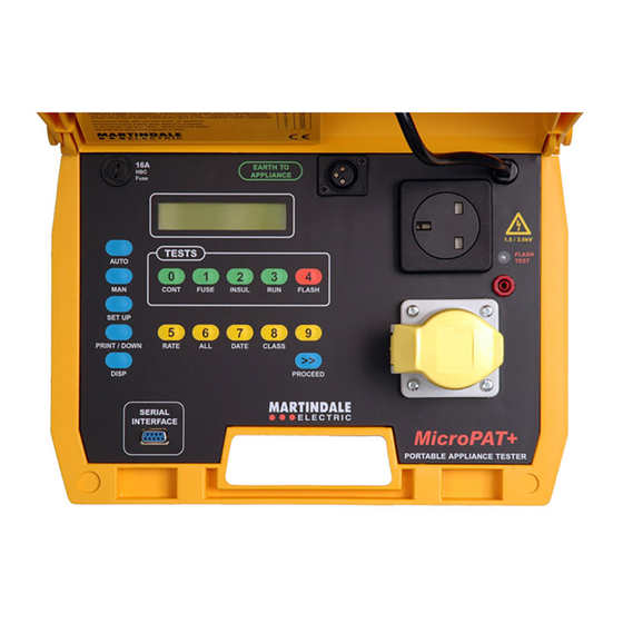
MICROPAT+
PAT TESTER
MARTINDALE
E L E C T R I C
Trusted by professionals
FIRMWARE
VERSION
6.1
ONWARDS
Advertisement
Table of Contents

Related Manuals for MARTINDALE MICROPAT+


Summary of Contents for MARTINDALE MICROPAT+
- Page 1 Check out what else you can get from Martindale: 18th Edition Testers Non-trip Loop Testers Accessories Pat Testers & Accessories Calibration Equipment Phase Rotation Testers Continuity Testers Proving Units Electricians’ Kits Socket Testers Environmental Products Thermometers & Probes INSTRUCTIONS Full Calibration & Repair Service...
- Page 2 SAFETY INFORMATION: Always read before proceeding. 5. Warranty This Martindale product is warranted to be free from defects in material and WARNING workmanship under normal use and service. The warranty period is 2 years and begins on the date of receipt by the end user. This warranty extends only to the...
-
Page 3: Maintenance
Fuse Rating The recommended calibration interval is 12 months. Insulation Martindale Electric will carry out routine calibration (on a chargeable basis) if the Run (Load) instrument is returned, carriage paid, to the address on the final page of this Earth Leakage document. - Page 4 1. INTRODUCTION When the battery is nearly drained, records will be lost or only maintained for a short time and if this occurs the battery must be replaced. This battery is not user replaceable and should only be replaced by qualified personnel. To ensure maximum protection of instrument records they should be transferred to a permanent copy on a daily basis.
- Page 5 pressing the CLASS key. When the PROCEED key is pressed, if a Class I test is 1.2 Earth Continuity specified, the display indicates the continuity test parameters. Pressing the For this test a voltage of 6V AC is applied between the earth pin of the plug of the PROCEED key initiates the AUTO TEST.
-
Page 6: Specifications
(see fuse test). If to be entered via a bar code reader (available separately from Martindale Electric). the appliance is known to have a high initial current which will rapidly fall to a steady value within the fuse rating then continue the test by releasing then re- 1.8 Unpacking &... - Page 7 and then the user I.D. will appear as already described. The prompt to enter the INSULATION TEST test code will now be displayed. A number obtained from the “Table of Codes for Test Voltage: 500VDC -0%, + 20% at 0.5MΩ Test Parameters”...
- Page 8 Serial interface: Printer/computer output using a 9 pin ‘D’ type basis but should only be used for type testing or after major repairs have been connector carried out which may have modified the characteristic insulation properties of the Pin 9: +5V appliance.
-
Page 9: Operation
tested, this will either be Class I or Class II and the pass test limit. If the displayed 2.3 Environmental Specification type does not match the appliance to be tested then press the CLASS key to change displayed type. TEMPERATURE Operating: 0°C to 35°C Press the PROCEED key to move onto the next display. - Page 10 a) Set Class: a) Earth Continuity Press the SET UP key. The display will show the setting options. By pressing the This test is only required for earthed (Class I) appliances. The resistance of the CLASS key, the class menu is displayed. Repeated pressing of the CLASS key earth circuit in the appliance and associated mains wire and plug is displayed.
- Page 11 The Print/Disp options are as follows: a) All SET UP:- CONTINUITY Selecting this option by pressing the ALL key when the all option is displayed will TEST CURRENT 25 AMP cause all the records stored to be output to the display/printer. b) Appliance ID Selecting this option by pressing the PROCEED key will result in the display prompting for the I.D.
-
Page 12: Set Up Date
date setting by pressing and releasing the DATE key. The display will show the last date set with a cursor under the first digit to be changed (see Fig. 7). Change Either press the ALL key to accept the displayed option or press the DISP key to the first pair or numbers in the date shown if required then press the PROCEED show the next option which is the ‘Appliance ID’...
Need help?
Do you have a question about the MICROPAT+ and is the answer not in the manual?
Questions and answers