Table of Contents
Advertisement
CONFORMS TO:
EN 61000-6-2:2005
EN 61000-6-3:2007 + A1:2011
AS/NZS 60000-6-3:2012
FCC CFR 47 Part 15 Subpart B
This device complies with part 15 of the FCC
rules. Operation is subject to the following two
conditions: 1) This device may not cause harmful
interference, and 2) This device must accept any
interference received, including interference that
may cause undesired operations.
THIS MANUAL INCLUDES IMPORTANT SAFETY INSTRUCTIONS FOR MODEL SB3000i
© Blue Sky Energy, Inc. 2017
SB3000i
(SOLAR BOOST™ 3000i MPPT)
12 VOLT 30/22 AMP MAXIMUM POWER POINT TRACKING
PHOTOVOLTAIC CHARGE CONTROLLER
NSTALLATION AND OPERATION MANUAL
I
SAVE THESE INSTRUCTIONS.
COVERED UNDER ONE OR MORE OF THE FOLLOWING US PATENTS
6,111,391 • 6,204,645
430-0034 C
Advertisement
Table of Contents

Related Manuals for BLUE SKY SOLAR BOOST 3000i MPPT


Summarization of Contents
IMPORTANT SAFETY INSTRUCTIONS
PERSONAL PRECAUTIONS
General safety measures when working with batteries, including protection against explosion and acid contact.
CHARGER LOCATION & INSTALLATION
Guidelines for placing and setting up the charger, emphasizing safe environments and proper wiring.
PREPARING TO CHARGE
Steps to take before initiating battery charging, such as ensuring battery ventilation and correct water levels.
PRODUCT DESCRIPTION
PART NUMBERS AND OPTIONS
List of available product models and optional accessories for the charge controller.
OPERATION
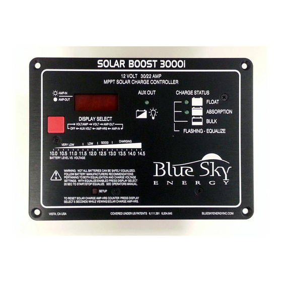
CHARGE STATUS INDICATION
How the device signals its charging mode and provides an indication of battery state of charge.
DIGITAL DISPLAY
Description of the front panel display functions, indicators, and automatic night dimming feature.
SOLAR CHARGE AMP-HOUR COUNTER
Tracks total PV amp-hours produced since the counter was last cleared.
BATTERY LEVEL GRAPHIC
Visual representation of approximate battery level based on battery voltage.
FRONT PANEL OPERATION & INDICATORS
Overview of physical controls and visual indicators on the unit's front panel.
3-STAGE CHARGE CONTROL
Explanation of the automatic Bulk, Absorption, and Float charging stages.
ABSORPTION CHARGE
Details on the absorption charging phase, its voltage, and duration.
FLOAT CHARGE
Information on maintaining the battery in a fully charged state with a lower voltage.
2-STAGE CHARGE CONTROL
Configuration option for a two-stage charging process, disabling the Float stage.
OUTPUT CURRENT LIMIT
How the unit automatically limits output current when PV power exceeds controller ratings.
OPTIONAL TEMPERATURE COMPENSATION
How battery temperature affects charge voltage settings when using an optional sensor.
EQUALIZATION
Process of applying a high charge voltage to equalize battery cells and maintain specific gravity.
MAXIMUM SETPOINT VOLTAGE LIMIT
Setting a ceiling on charge voltage to prevent overcharging or damage to connected equipment.
MAXIMUM POWER POINT TRACKING (MPPT)
Explanation of the MPPT technology for enhancing charge current by optimizing PV panel output.
PANEL TEMPERATURE AND THERMAL PROTECTION
How heat affects operation and the unit's thermal protection mechanisms.
MULTIPLE CHARGE CONTROLLERS ON THE IPN NETWORK
System expansion capabilities using multiple controllers networked together.
INSTALLATION
CHARGE AND LOAD CONTROL SETTINGS
Factory default and customizable charge and load control parameters for the unit.
AS SHIPPED FACTORY DEFAULT SETTINGS
Overview of the unit's default configuration parameters.
RESTORING AS SHIPPED FACTORY DEFAULT SETTINGS
Procedure to reset the unit to its original factory default settings.
CHANGING CHARGE AND LOAD CONTROL SETTINGS
Instructions on how to view and modify the unit's operational settings.
SELECTING PV MODULES
Guidance on choosing appropriate solar panels for optimal performance with the controller.
MOUNTING
Instructions for physically installing the charge controller, including ventilation requirements.
BATTERY AND PV WIRING
Guidelines for connecting batteries and PV modules, including wire gauge and terminal torque.
OPTIONAL BATTERY TEMPERATURE SENSOR
Instructions on how to install and use the optional battery temperature sensor for compensation.
AUXILIARY OUTPUT
Description of the auxiliary output functions and their configurations.
AUXILIARY BATTERY CHARGE
Using the auxiliary output to charge a secondary battery, prioritized after the main battery.
LOAD CONTROLLER
Using the auxiliary output to control loads with Low Voltage Disconnect (LVD).
DUSK-TO-DAWN LIGHTING CONTROL
Setting up the auxiliary output for lighting control based on ambient light and timers.
BATTERY & PV POWER CONNECT / DISCONNECT ORDER
Correct sequence for applying and removing power to the unit to prevent damage.
INSTALLING A MULTI-CONTROLLER SYSTEM USING THE IPN NETWORK
MULTI-CONTROLLER WIRING AND SETUP
Connecting multiple controllers for coordinated charging and system expansion.
TROUBLESHOOTING GUIDE
COMPLETELY DEAD, DISPLAY BLANK
Diagnosing issues when the unit shows no activity and the display is blank.
DISPLAY VERY DIM
Troubleshooting a dim or faint display, often related to charge status.
ALL DISPLAY SEGMENTS & LED INDICATORS STUCK ON
Resolving issues where all display segments and indicators remain illuminated.
UNIT WILL NOT SWITCH TO CHARGE ON STATE
Diagnosing why the unit fails to start charging, checking PV voltage and battery connection.
UNIT WILL NOT STAY IN A CHARGE ON STATE
Addressing problems where the unit stops charging unexpectedly or cycles frequently.
CHARGE STATUS INDICATOR ON BUT NO OUTPUT CHARGE CURRENT
Troubleshooting when charge is indicated but no current flows to the battery.
CHARGE OFF AT HIGH AMBIENT TEMPERATURE
Reasons for the unit shutting down or cycling off due to high internal or ambient temperature.
CHARGE CURRENT IS LOWER THAN EXPECTED
Investigating causes for lower-than-expected charge current during operation.
MPPT CURRENT BOOST IS LESS THAN EXPECTED
Diagnosing reduced MPPT performance, which may be due to panel conditions or wiring.
SYSTEM APPEARS TO OPERATE OK, BUT WILL NOT SWITCH BETWEEN BULK, ABSORPTION & FLOAT
Issues related to charge stage transitions not occurring as expected.
TEMPERATURE COMPENSATION OF CHARGE VOLTAGE DOES NOT WORK
Troubleshooting problems with the temperature sensor function affecting charge voltage.
AUXILIARY BATTERY NOT BEING CHARGING
Resolving issues where the auxiliary battery is not receiving charge.
AUXILIARY BATTERY VOLTAGE NOT DISPLAYING CORRECTLY
Diagnosing incorrect voltage readings for the auxiliary battery.
Need help?
Do you have a question about the SOLAR BOOST 3000i MPPT and is the answer not in the manual?
Questions and answers