Table of Contents
Advertisement
SOLAR BOOST™ 2000E
25AMP 12VDC MAXIMUM POWER POINT TRACKING
PHOTOVOLTAIC CHARGE CONTROLLER
INSTALLATION AND OPERATION
MANUAL
THIS MANUAL INCLUDES IMPORTANT SAFETY INSTRUCTIONS FOR MODEL SB2000E
SAVE THESE INSTRUCTIONS.
COVERED UNDER ONE OR MORE OF THE FOLLOWING US PATENTS
6,111,391
© Blue Sky Energy, Inc. 2011
430-0012 H
Advertisement
Table of Contents

Related Manuals for BLUE SKY SOLAR BOOST 2000E


Summary of Contents for BLUE SKY SOLAR BOOST 2000E
- Page 1 25AMP 12VDC MAXIMUM POWER POINT TRACKING PHOTOVOLTAIC CHARGE CONTROLLER INSTALLATION AND OPERATION MANUAL THIS MANUAL INCLUDES IMPORTANT SAFETY INSTRUCTIONS FOR MODEL SB2000E SAVE THESE INSTRUCTIONS. COVERED UNDER ONE OR MORE OF THE FOLLOWING US PATENTS 6,111,391 © Blue Sky Energy, Inc. 2011 430-0012 H...
-
Page 2: Table Of Contents
Blue Sky Energy - Solar Boost 2000E TABLE OF CONTENTS IMPORTANT SAFETY INSTRUCTIONS ..........................2 PRODUCT DESCRIPTION..............................3 Part Numbers and Options ............................. 3 OPERATION ..................................3 Charge Control ............................... 4 Charge Status Indicator ............................3 Battery Level Graphic ............................. 4 Equalization ................................ -
Page 3: Important Safety Instructions
Installation and Operation Manual IMPORTANT SAFETY INSTRUCTIONS This manual contains important instructions for Model SB2000E SAVE THESE INSTRUCTIONS 1. Refer installation and servicing to qualified service personnel. High voltage is present inside unit. Incorrect installation or use may result in risk of electric shock or fire. -
Page 4: Product Description
If PV power generation is too low and/or load current is too high for there to be at least 2 amps of net charge current available per 100 amp-hours of battery capacity the Solar Boost 2000E may be unable to hold battery voltage at the desired charge voltage setpoint. This will cause a discharged condition to be displayed even though the battery may be highly charged. -
Page 5: Battery Level Graphic
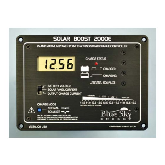
Installation and Operation Manual The 2000E front panel serves as a heat sink for power control devices. It is normal for the front panel to be quite warm to the touch during operation while delivering high charge current. PANEL LAYOUT Figure 1 BATTERY LEVEL GRAPHIC The 2000E also provides a battery level graphic on the front panel which indicates approximate battery level versus battery voltage. -
Page 6: Optional Temperature Compensation
Blue Sky Energy - Solar Boost 2000E OPTIONAL TEMPERATURE COMPENSATION The charge voltage required by flooded or sealed (AGM or GEL) lead-acid chemistry batteries changes with battery temperature. Temperature compensation of charge voltage leads to improved battery performance and life, and decreased battery maintenance. Automatic temperature compensation can be provided using the optional battery temperature sensor p/n 930-0022-20. -
Page 7: Selecting Pv Modules
30.0 millivolts/°C (–5.00mV/°C/cell) setting. NiCd and many lead-acid chemistry AGM type batteries require the –20.0 millivolts/°C (–3.33mV/°C/cell) setting. WARNING: Do not attach a sensor or any connections other than Blue Sky Energy battery temperature sensor p/n 930-0022-20 to the temperature sensor terminals. Be certain to observe proper RED/BLK polarity as shown in Figure 3. The 2000E cannot properly limit and control battery voltage if temperature compensation is enabled with the sensor installed reverse polarity. -
Page 8: Setting Charge Voltage
Blue Sky Energy - Solar Boost 2000E SETUP AND WIRING DIAGRAM The 2000E cannot limit and control battery voltage if temperature compensation is enabled with sensor installed reverse polarity. Output charge current will be disabled if temperature compensation is enabled without sensor installed. -
Page 9: Troubleshooting Guide
Installation and Operation Manual functioning and adjustment can be made. Verify that the LED remains on at the maximum current adjustment point, and as you check for a slight drop in current on either side of the maximum point. If LED does not remain on, MPPT is not operating due to a combination of high PV temperature and/or high battery voltage. -
Page 10: Specifications
FIVE YEAR LIMITED WARRANTY Blue Sky Energy, Inc. (hereinafter BSE), hereby warrants to the original consumer purchaser, that the product or any part thereof shall be free from defects due to defective workmanship or materials for a period of five (5) years subject to the conditions set forth below. - Page 11 Blue Sky Energy - Solar Boost 2000E MOUNTING TEMPLATE For product or purchasing inquiries contact: Figure 4 www.ecodirect.com...
Need help?
Do you have a question about the SOLAR BOOST 2000E and is the answer not in the manual?
Questions and answers
My solar controller is continuously clicking. Why is it doing that and what can I do to stop it?