Table of Contents
Advertisement
Quick Links
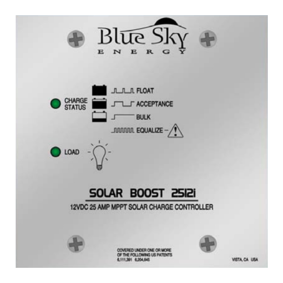
SOLAR BOOST™ 2512i(X)
25AMP 12VDC MAXIMUM POWER POINT TRACKING
PHOTOVOLTAIC CHARGE CONTROLLER
INSTALLATION AND OPERATION
MANUAL
THIS MANUAL INCLUDES IMPORTANT SAFETY INSTRUCTIONS FOR MODELS
SB2512i and SB2512iX, SAVE THESE INSTRUCTIONS.
COVERED UNDER ONE OR MORE OF THE FOLLOWING US PATENTS
6,111,391
6,204,645
© Blue Sky Energy, Inc. 2011
430-0021 E
Advertisement
Table of Contents

Subscribe to Our Youtube Channel
Summary of Contents for BLUE SKY Solar Boost 2512i
- Page 1 PHOTOVOLTAIC CHARGE CONTROLLER INSTALLATION AND OPERATION MANUAL THIS MANUAL INCLUDES IMPORTANT SAFETY INSTRUCTIONS FOR MODELS SB2512i and SB2512iX, SAVE THESE INSTRUCTIONS. COVERED UNDER ONE OR MORE OF THE FOLLOWING US PATENTS 6,111,391 6,204,645 © Blue Sky Energy, Inc. 2011 430-0021 E...
-
Page 2: Table Of Contents
Blue Sky Energy - Solar Boost 2512i and 2512iX TABLE OF CONTENTS IMPORTANT SAFETY INSTRUCTIONS ..........................2 PRODUCT DESCRIPTION..............................3 Features Omitted in the Solar Boost 2512i ......................3 Part Numbers and Options............................. 3 OPERATION ..................................3 Charge Status Indicator............................3 Auxiliary Output Indicator ............................ -
Page 3: Important Safety Instructions
Installation and Operation Manual IMPORTANT SAFETY INSTRUCTIONS This manual contains important instructions for Models SB2512i and SB2512iX SAVE THESE INSTRUCTIONS 1. Refer installation and servicing to qualified service personnel. High voltage is present inside unit. Incorrect installation or use may result in risk of electric shock or fire. -
Page 4: Product Description
FEATURES OMITTED IN THE SOLAR BOOST 2512i The following features described in this manual are omitted in the lower cost Solar Boost 2512i version of the product. See Figure 3 for omitted connectors and setup selectors. Battery Temperature sensor input... -
Page 5: Three Stage Charge Control
Installation and Operation Manual THREE STAGE CHARGE CONTROL The 2512 is factory configured for a three stage charging process, Bulk, Acceptance and Float. The three stage charge process provides a somewhat higher charge voltage to charge the battery quickly and safely. Once the battery is fully charged a somewhat lower voltage is applied to maintain the battery in a fully charged state without excessive water loss. -
Page 6: Current Limit
Blue Sky Energy - Solar Boost 2512i and 2512iX CURRENT LIMIT If PV input power is high enough to produce more than 25 amps of output current, the 2512 will automatically prevent output current from exceeding 25 amps. Note that when the 2512 exits current limit, it will briefly show Acceptance on the Charge Status Indicator even though battery voltage may be low. -
Page 7: Electrostatic Handling Precautions
Installation of the optional battery temperature sensor enables temperature compensation of all charge voltage setpoints. In a multi-controller system a single temperature sensor must connect to the IPN master. Do not attach a sensor or connections other than Blue Sky Energy battery temperature sensor p/n... -
Page 8: Battery And Pv Wiring
Blue Sky Energy - Solar Boost 2512i and 2512iX BATTERY AND PV WIRING A desirable installation will produce a total system wiring voltage drop of 3% or less. The lengths shown in Table 2 are one way from the PV modules to the battery with the 2512 located along the path. -
Page 9: Auxiliary Battery Charge
Installation and Operation Manual AUXILIARY BATTERY CHARGE – DIP #3 OFF The auxiliary charge function is used to charge an auxiliary battery of the same voltage as the primary battery. If the primary battery is charging in Acceptance or Float, up to 2 amps is diverted to the auxiliary battery at the same charge voltage. Auxiliary battery charge is disabled during Bulk or Equalization. Use 14 awg wire to minimize voltage drop and 25 amp maximum over current protection. -
Page 10: Ipn Network Address
Blue Sky Energy - Solar Boost 2512i and 2512iX IPN NETWORK WIRING FIGURE 5 IPN Network Address – DIP’s #1, #2 & Jumper A2 (Omitted on SB2512i) A single controller must be set to IPN network address 0 (zero). In a multi-controller system one controller must be set to address 0 (zero) to serve as the master. -
Page 11: Auxiliary Output
Installation and Operation Manual TROUBLESHOOTING GUIDE SYMPTOM PROBABLE CAUSE ITEMS TO EXAMINE OR CORRECT Completely dead, No battery power Battery disconnected, overly discharged, or connected reverse polarity. Battery powers the 2512, optional display blank not PV. Unit will not turn ON PV disconnected or low in voltage PV must supply 0.10 amps at greater than battery voltage to begin charge. -
Page 12: Specifications
FIVE YEAR LIMITED WARRANTY Blue Sky Energy, Inc. (hereinafter BSE), hereby warrants to the original consumer purchaser, that the product or any part thereof shall be free from defects due to defective workmanship or materials for a period of five (5) years subject to the conditions set forth below.


Need help?
Do you have a question about the Solar Boost 2512i and is the answer not in the manual?
Questions and answers