
Related Manuals for Zanotti FZ229


Summarization of Contents
1. Safety Recommendations
Hand Protection Warning
Safety warning about using gloves for protection against cuts.
Explosive Environments Warning
Warning that the unit is unsuitable for explosive environments.
Salty Environments Warning
Warning about using the unit in salty environments and the need for protection.
Refrigerant Discharge Warning
Warning against discharging refrigerant into the atmosphere.
Safe Unit Usage Suggestions
Cleaning Precautions
Caution against using water or steam for cleaning to avoid damage to electrical components.
Maintenance Safety
Warning that cleaning and maintenance must be performed with the unit switched off.
First Aid for Freezing
Instructions for first aid in case of freezing due to refrigerant contact.
Refrigerant Oil Handling
Information regarding refrigerant oil handling and skin contact precautions.
1.1 Warranty and Maintenance
Warranty Information
Information regarding product warranty and manufacturer's right to modify products.
Maintenance Guidelines
Importance of maintenance as per manufacturer's timing and authorized repair shops.
1.3 Safety Information
Closed Environment Operation
Warning about using the 'MAINS' function in closed environments to avoid gas poisoning.
Moving Parts Safety
Caution regarding maintenance work while the system is in motion and attention to moving parts.
Hot Surfaces Warning
Warning about hot components like compressor, condenser, and piping after operation.
Electrical and Battery Safety
Electrical Shock Precautions
Precautions related to electric shocks, including turning off power before opening control boxes.
Battery Maintenance Guidelines
Guidelines for checking and maintaining vehicle batteries for the unit.
2. Warning and Attention Plates
Refrigerant Type R 404 A
Identifies the refrigerant type used.
Condensate Drain Line Indicator
Indicates the condensate drain line.
Hot/Cold Parts Caution
Warning about hot or cold components.
Pre-Operation Switch-Off
Crucial safety instruction to switch off the unit before operation.
Electrocution Danger Warning
Warning about the danger of electrocution.
Direction of Rotation Indicator
Indicates the direction of rotation for components.
Supply Cable Wire Colours
Information on the colours of supply cable wires.
Condenser Cleaning Reminder
Important attention note to clean the condenser periodically.
3. Available Models
FZ213 Technical Features
Technical features for model FZ213.
FZ214 Technical Features
Technical features for model FZ214.
3.1 Main Technical Features
FZ218 Technical Features
Technical features for model FZ218.
FZ219 Technical Features
Technical features for model FZ219.
4. Road Compressor Kit Installation
Road Compressor Fitting
Instructions for fitting the road compressor kit.
Kit SFZ213 / SFZ214 Installation
SFZ213/SFZ214 Component List
List of components for the SFZ213/SFZ214 kit.
Kit SFZ218 Installation
SFZ218 Component List
List of components for the SFZ218 kit.
Kit SFZ219 Installation
SFZ219 Component List
List of components for the SFZ219 kit.
Kit SFZ221 Installation
SFZ221 Component List
List of components for the SFZ221 kit.
Kit SFZ228 Installation
SFZ228 Component List
List of components for the SFZ228 kit.
Kit SFZ229 Installation
SFZ229 Component List
List of components for the SFZ229 kit.
4.1 Unit Installation Procedure
Condenser Fitting Details
Specific details and steps for fitting the condenser unit.
Control Box Placement
Location and placement advice for the refrigeration unit control box.
Cable and Tubing Contact Check
Critical check to prevent contact between electric cables and high-pressure tubing.
Professional Installation Benefits
Professional installation ensures effective system operation, including vacuum and leak checks.
5. Unit Dimensions and Fitting
FZ213 Dimensions and Fitting
Dimensional and fitting information for the FZ213 model.
FZ214 Dimensions and Fitting
FZ214 Dimensions and Fitting
Dimensional and fitting information for the FZ214 model.
FZ218 Dimensions and Fitting
FZ218 Dimensions and Fitting
Dimensional and fitting information for the FZ218 model.
FZ219 Dimensions and Fitting
FZ219 Dimensions and Fitting
Dimensional and fitting information for the FZ219 model.
FZ221 Dimensions and Fitting
FZ221 Dimensions and Fitting
Dimensional and fitting information for the FZ221 model.
FZ228 Dimensions and Fitting
FZ228 Dimensions and Fitting
Dimensional and fitting information for the FZ228 model.
FZ229 Dimensions and Fitting
FZ229 Dimensions and Fitting
Dimensional and fitting information for the FZ229 model.
5. Cooling Circuit and Connection Details
Refrigerant Diagram Key
Key explaining the components and symbols in the refrigerant diagram.
FZ 213 Unit Components
FZ 213 Condensing Parts Diagram
Diagram of condensing parts for the FZ 213 model.
FZ 213 Compressor Parts Diagram
Diagram of compressor parts for the FZ 213 model.
FZ 213 Evaporating Parts Diagram
Diagram of evaporating parts for the FZ 213 model.
FZ 214 Unit Components
FZ 214 Condensing Parts Diagram
Diagram of condensing parts for the FZ 214 model.
FZ 214 Compressor Parts Diagram
Diagram of compressor parts for the FZ 214 model.
FZ 214 Evaporating Parts Diagram
Diagram of evaporating parts for the FZ 214 model.
FZ 218 Unit Components
FZ 218 Condensing Parts Diagram
Diagram of condensing parts for the FZ 218 model.
FZ 218 Compressor Parts Diagram
Diagram of compressor parts for the FZ 218 model.
FZ 218 Evaporating Parts Diagram
Diagram of evaporating parts for the FZ 218 model.
FZ 219 Unit Components
FZ 219 Condensing Parts Diagram
Diagram of condensing parts for the FZ 219 model.
FZ 219 Compressor Parts Diagram
Diagram of compressor parts for the FZ 219 model.
FZ 219 Evaporating Parts Diagram
Diagram of evaporating parts for the FZ 219 model.
FZ 221 Unit Components
FZ 221 Condensing Parts Diagram
Diagram of condensing parts for the FZ 221 model.
FZ 221 Compressor Parts Diagram
Diagram of compressor parts for the FZ 221 model.
FZ 221 Evaporating Parts Diagram
Diagram of evaporating parts for the FZ 221 model.
FZ 228 Unit Components
FZ 228 Condensing Parts Diagram
Diagram of condensing parts for the FZ 228 model.
FZ 228 Compressor Parts Diagram
Diagram of compressor parts for the FZ 228 model.
FZ 228 Evaporating Parts Diagram
Diagram of evaporating parts for the FZ 228 model.
FZ 229 Unit Components
FZ 229 Condensing Parts Diagram
Diagram of condensing parts for the FZ 229 model.
FZ 229 Compressor Parts Diagram
Diagram of compressor parts for the FZ 229 model.
FZ 229 Evaporating Parts Diagram
Diagram of evaporating parts for the FZ 229 model.
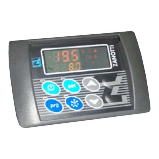
7. Controller Description
Display and Button Functions
Description of the controller's display elements and button functions.
ON/OFF Button
Description of the ON/OFF button and its function.
SET Button
Description of the SET button for setting the work set point.
Programming Button
Description of the PROGRAMMING BUTTON to access programming mode.
Manual Defrost Button
Description of the MANUAL DEFROST BUTTON.
Up/Down Buttons
Description of UP/DOWN buttons for parameter and set point adjustment.
Temperature Unit LED (°C/°F)
Explanation of the °C or °F LED.
Mode Indicators (Hot/Cold)
Explanation of the HOT MODE and COLD MODE LEDs.
Defrost and Stand-by LEDs
Explanation of the DEFROST and STAND-BY LEDs.
Alarm and Road LEDs
Explanation of the ALARM and ROAD LEDs.
Fan Status LEDs
Explanation of the CONDENSER FAN and EVAPORATOR FAN LEDs.
Display Functions (Temp/Alarms)
Description of the main display for cold room temperature and alarms.
7.2 Setting Work Set Point
Set Point Parameters (Set, Set2)
Parameters for setting the desired temperature and secondary set point.
Operating Mode Parameter (FuS)
Parameter for selecting operating modes (CL, C-H, HPU).
Hysteresis and Set Point Limits (Dt, IS, SS)
Parameters for hysteresis, minimum, and maximum set points.
Sensor Calibration and Temperature Alarms (OF, AL, AH, dA, SA, ALd)
Parameters for sensor calibration, temperature alarms, and differentials.
Defrost Parameters (Tdf, dS, Fdt, Fnd, EdA)
Parameters related to defrost mode, time, dripping, fan delay, and alarm cut-out.
Interval and Display Parameters (Sd, dF, dFd, dAd)
Parameters for anti-short cycle, defrost intervals, and display delays.
Battery Voltage Parameters (Bt, PAb, Ab, Abd)
Parameters for battery voltage selection and alarm differentials.
Clutch and Alarm Delay Parameters (tF, bb)
Parameters for standby clutch delay and start delay after alarm.
Unit Unit and Polarity Parameters (tS, rES, LPP, LPn, LPd, HPP, HPn, HPd, dFP, HtP, Htn, Htd, HOP)
Parameters for unit selection, polarity, switch interventions, and delays.
8. Operation Modes
Road Operation Mode
Instructions for operating the unit in road mode.
Stand-by Operation Mode
Instructions for operating the unit in stand-by mode.
Automatic Operation and Modes
Explanation of automatic operation and different operating modes with icon indicators.
Defrost Cycle Operation
Details on automatic and manual defrost cycles, including icon indicators.
Unit Alarms and Warnings
Explains low pressure, high pressure, overload, sensor failure, and temperature alarms.
Alarms and Disposal
Battery Voltage and Supply Alarms
Explanation of battery voltage alarm in road mode and supply alarm.
Wiring Diagram Reference
Reference to the enclosed wiring diagram for unit specifics.
Ordering Spare Parts
Instructions on how to order spare parts, referencing the unit plate number.
Worn Parts Replacement Warning
Warning that worn parts must be replaced by qualified personnel or the manufacturer.
Packing Disposal Guidelines
Guidelines for disposing of packing materials according to local regulations.
Unit Disposal and Refrigerant Handling
Instructions for proper disposal of unit components and refrigerant.
Refrigerant Discharge Prohibition
Warning against discharging refrigerant into the atmosphere and proper disposal methods.
13. Wiring Diagram Component Labels
BA to K2 Labels
Labels for wiring diagram components from BA to K2.
K39 to KSF Labels
Labels for wiring diagram components from K39 to KSF.
Electric Motor and Motor Labels (M1 to M11)
Labels for electric motors and related components from M1 to M11.
MCC, P1MX, PMI Labels
Labels for MCC, P1MX (pressure switch), and PMI components.
Wiring Diagram Component Labels Continued
Switch and Transformer Labels (LOW PRESSURE SWITCH to TAL)
Labels for switches and transformer components.
Thermo-Contact and Connector Labels (TK, X, YC)
Labels for thermo-contact and main connector.
Solenoid Labels (YF, YFH, YFR, YI, YS)
Labels for various solenoid components related to cycles and heating.
Need help?
Do you have a question about the FZ229 and is the answer not in the manual?
Questions and answers