
Related Manuals for Zanotti FZ214


Summary of Contents for Zanotti FZ214
- Page 1 FZ213 - FZ214 FZ218 - FZ219 - FZ221 FZ228 - FZ229 LIBRETTO DI INSTALLAZIONE INSTALLATION MANUAL MANUEL D’INSTALLATION MONTAGEANLEITUNG LIBRO DE INSTALACIÓN...
-
Page 2: Table Of Contents
CONTENTS Safety recommendations Warranty Maintenance Safety information Table of warning and attention plates Models available Main technical features Installation instructions 4.1. Display description 4.2. Instructions for battery connection to feeder Unit dimensions and fitting Cooling circuit and connections details Controller description 7.1 Display descriptions 7.2 Set point setting and changing 7.3 Programming parameters... -
Page 3: Safety Recommendations
Thank you for choosing Uniblock. Please read these instructions carefully. They provide details and advice on the correct method of installing, using and maintaining this unit, in order to obtain maximum reliability, efficiency and long life. 1. Safety recommendations When installing and using the unit please follow the recommendations listed here below. •... - Page 4 For safe use of the unit, we suggest: ATTENTION • Do not use water or steam when cleaning as the electrical components may be damaged. • Keep condenser and evaporator clean. • Stand-by operation in enclosed places: ensure good ventilation to the condenser. •...
-
Page 5: Warranty
These indications do not constitute an approval or a warranty on the part of ZANOTTI S.p.A. regarding the integrity of the chiller. It may happen that some of the adaptable elements described in the installation procedure do not correspond. If this should occur, contact our service office. - Page 6 • If necessary, clean the parts in question. • Do not let children operate the refrigeration system. ELECTRIC SHOCKS • Before opening the electric control box door, make sure that the power is turned off. • Before carrying out any soldering work on the refrigeration system, disconnect the vehicle battery. •...
-
Page 7: Table Of Warning And Attention Plates
2. Table of warning and attention plates Modello Year of manufacture Model ZANOTTI unit code ZANOTTI S.p.A. Serial number Via Martin L. King, nr. 30 46020 PEGOGNAGA (Mantova) - Italy Voltage Modello Run Absorption Model Matricola Serial Number Max Absorption... -
Page 8: Models Available
Air volume 900 m³/h Evaporator fan helicoidal type 12 Vdc direct supply Air volume 660 m³/h Main compressor 22 cm³ Electric motor (road) supply 230V/1 ~ /50Hz FZ214 Road Main Road cooling capacity T amb. 30 °C T box 0 °C 2627 W 1704W T amb. - Page 9 FZ221 Road Mains Cooling capacity T amb. 30 °C T box 0 °C 2879 W 2023 W T amb. 30 °C T box –20 °C 1692 W 842 W Road compressor 146 cm3 displacement Condenser fan helicoidal type 12 Vcc o 24 Vcc direct supply air volume 2000 m3/h evaporator fan helicoidal type 12 Vcc o 24 Vcc direct supply...
- Page 10 Kit SFZ213 / SFZ214 installation Component List Descrizione Codice Q.tà Descrizione Codice Q.tà Cable And Tube Pass. Ext. 3001242/A Pipe Trough 3CNL015 Closing Cable And Tube Pass. Int. 3001243/A Self-Threading Screw 4,8X22 3VTE221 Closing Gasket 3NST025 Internal Trough Bracket 3SFP012 Soldering Label 3ETA479 Trough Joint...
- Page 11 Compressor Component List Description Code Q.ty Graduated Oil Container 3CNO001 Label 3ETA647 Union 7/8 s.10 3RCR099 Union 3/4 s.08 3RCR090 Union 7/8 s.10 3RCR071 Union 3/4 s.08 3RCR070 Gasket O-R 16 3GUR028 Gasket O-R 12 3GUR027 Gasket O-R 08 3GUR026 Lot manuli Component List Description...
- Page 12 Kit SFZ218 installation Component List Descrizione Codice Q.tà Descrizione Codice Q.tà Cable And Tube Pass. Ext. 3001242/A Pipe Trough 3CNL015 Closing Cable And Tube Pass. Int. 3001243/A Self-Threading Screw 4,8X22 3VTE221 Closing Gasket 3NST025 Internal Trough Bracket 3SFP012 Soldering Label 3ETA479 Trough Joint 3GNE002...
- Page 13 Compressor Component List Description Codice Q.tà Graduated Oil Container 3CNO001 Label 3ETA647 Union 7/8 s.10 3RCR099 Union 3/4 s.08 3RCR090 Union 7/8 s.10 3RCR071 Union 3/4 s.08 3RCR070 Gasket O-R 16 3GUR028 Gasket O-R 12 3GUR027 Gasket O-R 08 3GUR026 Lot manuli Component List Description...
- Page 14 Kit SFZ219 installation Component List Descrizione Codice Q.tà Descrizione Codice Q.tà Cable And Tube Pass. Ext. 3001242/A T-Union 3TEE007 Closing Cable And Tube Pass. Int. 3001243/A Pipe Trough 3CNL015 Closing Gasket 3NST025 Self-Threading Screw 4,8X22 3VTE221 Soldering Label 3ETA479 Internal Trough Bracket 3SFP012 Nut M 10 3DDO070...
- Page 15 Compressor Component List Description Codice Q.tà Graduated Oil Container 3CNO001 Label 3ETA647 Union 7/8 s.10 3RCR099 Union 3/4 s.08 3RCR090 Union 7/8 s.10 3RCR071 Union 3/4 s.08 3RCR070 Gasket O-R 16 3GUR028 Gasket O-R 12 3GUR027 Gasket O-R 08 3GUR026 Lot manuli Component List Description...
- Page 16 Kit SFZ221 installation Component List Descrizione Codice Q.tà Descrizione Codice Q.tà Cable And Tube Pass. Ext. 3001242/A T-Union 3TEE007 Closing Cable And Tube Pass. Int. 3001243/A Pipe Trough 3CNL015 Closing Gasket 3NST025 Self-Threading Screw 4,8X22 3VTE221 Soldering Label 3ETA479 Internal Trough Bracket 3SFP012 Nut M 10 3DDO070...
- Page 17 Compressor Component List Description Codice Q.tà Graduated Oil Container 3CNO001 Label 3ETA647 Union 7/8 s.10 3RCR099 Union 3/4 s.08 3RCR090 Union 7/8 s.10 3RCR071 Union 3/4 s.08 3RCR070 Gasket O-R 16 3GUR028 Gasket O-R 12 3GUR027 Gasket O-R 08 3GUR026 Lot manuli Component List Description...
- Page 18 Kit SFZ228 installation Component List Description Code Q.ty Description Code Q.ty Cable And Tube Pass. Ext. 3001242/A Pipe Trough 3CNL015 Closing Cable And Tube Pass. Int. 3001243/A Self-Threading Screw 4,8X22 3VTE221 Closing Gasket 3NST025 Internal Trough Bracket 3SFP012 Soldering Label 3ETA479 Trough Joint 3GNE002...
- Page 19 Compressor Component List Description Code Q.ty Graduated Oil Container 3CNO001 Label 3ETA647 Union 7/8 s.10 3RCR099 Union 3/4 s.08 3RCR090 Union 7/8 s.10 3RCR071 Union 3/4 s.08 3RCR070 Gasket O-R 16 3GUR028 Gasket O-R 12 3GUR027 Gasket O-R 08 3GUR026 Lot manuli Component List Description...
- Page 20 Kit SFZ229 installation Component List Descrizione Codice Q.tà Descrizione Codice Q.tà Cable And Tube Pass. Ext. 3001242/A T-Union 3TEE007 Closing Cable And Tube Pass. Int. 3001243/A Pipe Trough 3CNL015 Closing Gasket 3NST025 Self-Threading Screw 4,8X22 3VTE221 Soldering Label 3ETA479 Internal Trough Bracket 3SFP012 Nut M 10 3DDO070...
- Page 21 Compressor Component List Description Codice Q.tà Graduated Oil Container 3CNO001 Label 3ETA647 Union 7/8 s.10 3RCR099 Union 3/4 s.08 3RCR090 Union 7/8 s.10 3RCR071 Union 3/4 s.08 3RCR070 Gasket O-R 16 3GUR028 Gasket O-R 12 3GUR027 Gasket O-R 08 3GUR026 Lot manuli Component List Description...
- Page 22 Unit installation procedure On the split system we advise you to install the condenser and the evaporator in different points; more precisely: · The condenser can be installed as "projecting part" (on the frontal wall of the van) or "on the roof" (on the roof of the vehicle).
- Page 23 Unit dimesions and fitting FZ213...
- Page 24 FZ214...
- Page 25 FZ218...
- Page 26 FZ219...
- Page 27 FZ221...
- Page 28 FZ228...
- Page 29 FZ229...
-
Page 30: Cooling Circuit And Connections Details
Coolingcircuit and connection details Refrigerant diagram key Compressor Pressure regulator valve Check valve Liquid sightglass High pressure switch Dehydrator filter Low pressure switch Condenser fan Condenser battery Heat exchanger Solenoid valve Thermostatic bulb Electric motor Evaporatting battery Condensing units Evaporator fan Evaporatorating units Thermostatic valve Compressor... - Page 31 FZ 213 Condensing parts FZ 213 Compressor parts FZ 213 Evaporating parts...
- Page 32 FZ 214 Condensing parts FZ 214 Compressor parts FZ 214 Evaporating parts...
- Page 33 FZ 218 Condensing parts FZ 218 Compressor parts FZ 218 Evaporating parts...
- Page 34 FZ 219 Condensing parts FZ 219 Compressor parts FZ 219 Evaporating parts...
- Page 35 FZ 221 Condensing parts FZ 221 Compressor parts FZ 221 Evaporating parts...
- Page 36 FZ 228 Condensing parts FZ 228 Compressor parts FZ 228 Evaporating parts...
- Page 37 FZ 229 Condensing parts FZ 229 Compressor parts FZ 229 Evaporating parts...
-
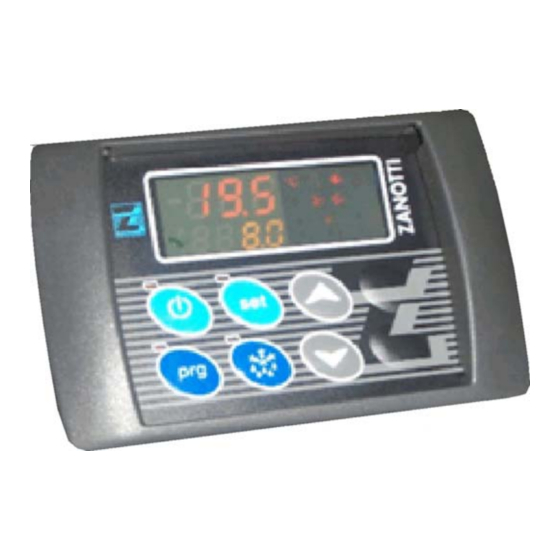
Page 38: Controller Description
Controller description Description of the display: 17. ON/OFF button: to switch on/off the unit (press 3 seconds). The red LED lights up when the unit is on. 18. SET button: to set the work set point of the unit. When the LED is on, setting is enabled. 19. - Page 39 7.2. Setting the work set point: Press the SET button: on the red display the current value flashes and Set1 appears on the yellow display; press the up/down buttons to change the current value. Press SET again or wait 10 seconds to save the new value. Programming the parameters To enter the programming mode press for 5 seconds.
-
Page 40: Operations
Operation Operation in road mode: Check that the punctiform LED on the display is on, showing that the unit is on. Start the vehicle engine and press the ON button for 3 seconds. Attention: when the vehicle is not in motion the refrigerating unit can not be used in road mode. -
Page 41: Wiring Diagram
Battery voltage alarm This alarm is only active when the unit operates in road mode. If battery voltage (sensored on key introduction) is lower than the value bt-Pab, a preliminary alarm PAb is activated which just indicates that there is an anomaly. - Page 42 13. Wiring diagram PHASE REVERSAL MOTOR M1 CONTACTOR ROOM PROBE RECTIFICATION CAPACITOR TIMER FOR MAINS FEEDER DELAY RUN CAPACITOR COND FAN CONTACTOR OR RELAY START CAPACITOR EVAP.FAN CONTACTOR OR RELAY HEATER EVAP.FAN CONTACTOR OR RELAY DISCHARGE HEATER EVAP.FAN CONTACTOR OR RELAY M1 MOTOR FUSE LOW TEMP.
- Page 43 LOW PRESSURE SWITCH SOLENOID CYCLE REVERSAL HIGH PRESSURE SWITCH ROAD CLUTCH TRANSFORMER STAND-BY CLUTCH THERMO-CONTACT INJECTION SOLENOID MAIN CONNECTOR HOT GAS SOLENOID SOLENOID HEATING CYCLE...
- Page 45 Zanotti S.p.A. Via M.L. King, 30 - 46020 Pegognaga (MN) Italy Tel. 0376.5551 Fax 0376.536554 Info@zanotti.com www.zanotti.com...
Need help?
Do you have a question about the FZ214 and is the answer not in the manual?
Questions and answers