
Related Manuals for VIPA 315-2AG13


Summarization of Contents
1 General
1.1 Copyright and Legal Information
Contains copyright notice, proprietary information, and usage restrictions for the document.
1.3 Safety Information
Provides essential safety guidelines for operating the CPU and related components.
1 About this Manual
Manual Objectives and Audience
Describes the manual's purpose, contents, and target audience for users.
Manual Structure
Explains the organization of the manual into chapters for self-contained topic descriptions.
2 Basics
2.1 User Safety Precautions
Details handling precautions for electrostatic sensitive modules and general safety measures.
2.2 CPU Operating Structure
Explains the CPU's operating structure, including cyclic, timer, and priority-based processing modes.
2 Basics
CPU Program Applications
Describes the division of the CPU program into system routine and user application.
CPU Operands
Details operand types for CPU programming: process image, bit memory, timers, counters, data blocks.
2 Basics
2.3 CPU 315-2AG13 Overview
Overview of CPU 315-2AG13, its SPEED7 technology, programming methods, and memory.
2 Basics
CPU Memory Management
Explains the CPU's integrated memory structure (load, code, data, work) and expansion options.
2 Basics
2.4 General Data
Covers interfaces, operation security, dimensions, and power supply specifications for the CPU.
2 Basics
Device Protection and Environmental Conditions
Details protection types, isolation, environmental specifications (climatic, mechanical), and mounting conditions.
2 Basics
EMC Standards and Immunity
Covers EMC standards for emitted interference and noise immunity, including specific test conditions.
3 Assembly and Installation Guidelines
3.1 Installation Dimensions
Provides dimensions for the CPU basic enclosure and installation requirements.
3 Assembly and Installation Guidelines
3.2 Standard Bus Assembly
Explains module assembly on a profile rail using a backplane bus connector.
3 Assembly and Installation Guidelines
3.3 Cabling and Approach
Details mounting, cabling steps, and electrical safety precautions for CPU and module installation.
3 Assembly and Installation Guidelines
3.4 Installation Guidelines
Provides guidelines for interference-free PLC deployment, EMC, and isolation management.
3 Assembly and Installation Guidelines
EMC Fundamentals and Rules
Defines EMC, lists interference causes, and outlines basic rules for ensuring electromagnetic compatibility.
4 Hardware Description
4.1 CPU Properties
Lists the integrated features and capabilities of the CPU 315-2AG13, including technology and interfaces.
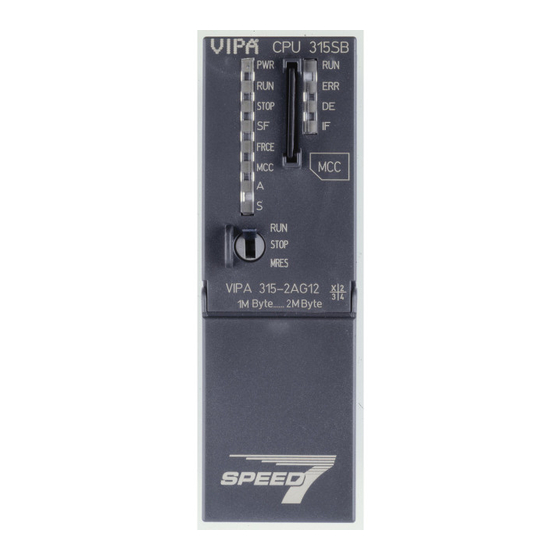
4 Hardware Description
4.2 CPU Structure and Interfaces
Details the CPU's physical structure, LEDs, switches, and key interfaces like MPI and Ethernet.
4 Hardware Description
CPU Interface Details
Explains power supply, MPI, Ethernet PG/OP, and PROFIBUS/PtP interfaces with their specifications.
4 Hardware Description
Memory Management and Storage
Covers memory division, storage media slot usage (MMC), and battery backup for RAM and clock.
4 Hardware Description
CPU Operating Modes and LEDs
Explains the operating mode switch and the meaning of CPU status LEDs for operation and diagnostics.
4 Hardware Description
4.3 Technical Data
Provides detailed technical specifications for the CPU 315-2AG13, including electrical and performance data.
4 Hardware Description
CPU Technical Data Summary
Lists data on memory, hardware configuration limits, command processing times, and data range characteristics.
4 Hardware Description
Block Data and Time Specifications
Details block counts, sizes, nesting depths, and time-related specifications like clock buffering.
4 Hardware Description
Communication Functions and Interfaces
Covers communication functions (PG/OP, S7) and details of Sub-D interfaces (RS485, MPI).
4 Hardware Description
MPI and PROFIBUS Master Functionality
Details MPI functionality (connections, speed) and PROFIBUS master capabilities (PG/OP, data exchange).
4 Hardware Description
PROFIBUS Slave and PtP Communication
Explains PROFIBUS slave functionality and point-to-point communication via RS485, including protocols.
4 Hardware Description
RJ45 Interface and Certifications
Specifies RJ45 interface details, housing, mechanical, environmental data, and UL508 certification.
5 Deployment CPU 315-2AG13
5.1 Assembly and Cabling Reference
Refers to Chapter 3 for detailed information on CPU assembly and cabling procedures.
5.2 CPU Start-up Behavior
Describes CPU start-up behavior upon power-on, including default, valid configuration, and empty battery states.
5 Deployment CPU 315-2AG13
5.3 Addressing Peripherals
Explains peripheral module addressing, I/O areas, process images, and maximum module configuration.
5 Deployment CPU 315-2AG13
5.4 CPU Hardware Configuration
Details CPU configuration using Siemens hardware configurator and automatic addressing functionality.
5 Deployment CPU 315-2AG13
5.5 I/O Module Hardware Configuration
Guides on configuring I/O modules after CPU setup and parameterizing them using SFCs.
5 Deployment CPU 315-2AG13
5.6 Ethernet PG/OP Channel Configuration
Covers Ethernet PG/OP channel configuration, assembly, initialization, and IP address assignment.
5 Deployment CPU 315-2AG13
Assigning IP Parameters
Step-by-step guide for assigning IP parameters for the Ethernet PG/OP channel via SIMATIC Manager.
5 Deployment CPU 315-2AG13
5.8 Setting Standard CPU Parameters
Explains parameter setting for the CPU using Siemens hardware configurator and lists supported parameters.
5 Deployment CPU 315-2AG13
CPU Startup and Memory Settings
Configures startup behavior, cycle/clock memory, and retentive memory settings for the CPU.
5 Deployment CPU 315-2AG13
Interrupts and Clock Settings
Covers interrupt handling, time-of-day/cyclic interrupts, and diagnostics/clock synchronization configurations.
5 Deployment CPU 315-2AG13
CPU Protection and DP/MPI Parameters
Sets CPU protection levels and details parameters for PROFIBUS DP and MPI interfaces.
5 Deployment CPU 315-2AG13
5.9 Setting VIPA Specific CPU Parameters
Guides on setting VIPA-specific parameters, including RS485 function, token watch, and remanence.
5 Deployment CPU 315-2AG13
SPEEDBUS.GSD Installation
Instructions for downloading and integrating the SPEEDBUS.GSD file into the hardware catalog.
5 Deployment CPU 315-2AG13
5.9.2 VIPA Specific Parameters
Details VIPA-specific parameters accessible via the CPU properties dialog, focusing on RS485 function.
5 Deployment CPU 315-2AG13
DP Synchronization Modes
Explains synchronization modes (SyncIn, SyncInOut, SyncOut) between DP master and CPU.
5 Deployment CPU 315-2AG13
5.10 Project Transfer Methods
Outlines methods for transferring projects to the CPU: MPI/PROFIBUS, Ethernet, and MMC.
5 Deployment CPU 315-2AG13
5.10.1 Transfer via MPI/PROFIBUS
Details project transfer via MPI/PROFIBUS, including interface, net structure, and cable requirements.
5 Deployment CPU 315-2AG13
5.10.2 Transfer via Ethernet
Explains project transfer via Ethernet, covering initialization and the transfer process.
5 Deployment CPU 315-2AG13
5.10.3 Transfer via MMC
Describes project transfer using MMC, including file naming conventions and transfer control.
5 Deployment CPU 315-2AG13
5.11 Access to Internal Web Page
Guides on accessing the CPU's internal web page via Ethernet for firmware and status information.
5.12 Operating Modes
5.12.1 Operating Mode Overview
Explains the four operating modes: STOP, START-UP, RUN, and HOLD, and their associated behaviors.
5.12 Operating Modes
Debugging with Breakpoints
Provides steps for setting and using breakpoints for program debugging and analyzing CPU state.
5.13 Overall Reset
Overall Reset Procedure
Explains how to perform an overall reset of the CPU, erasing user memory and returning to delivery state.
5.13 Overall Reset
Reset Methods
Details methods for performing an overall reset using the operating mode switch or SIMATIC Manager.
5.14 Firmware Update
Factory Reset After Update
Explains the importance of factory reset after firmware updates and cautions about potential CPU damage.
5.14 Firmware Update
Firmware Update Process
Guides on downloading firmware, transferring to MMC, and performing the update on the CPU.
5.15 Reset to Factory Setting
Factory Reset Procedure
Provides a detailed procedure for performing a factory reset on the CPU, including LED status indications.
5.16 Slot for Storage Media
Storage Media Access
Explains CPU access to storage media after reset/PowerON for project loading and command execution.
5.17 Memory Extension with MCC
MCC Memory Extension
Describes extending CPU memory using an MCC card and executing an overall reset for activation.
5.18 Extended Know-How Protection
VIPA Extended Protection
Details VIPA's extended know-how protection for secure block storage and transfer to a WLD file.
5.19 MMC-Cmd - Auto Commands
Command File Execution
Defines command file structure and execution conditions on MMC for automatic CPU operations.
5.20 VIPA Specific Diagnostic Entries
Monitoring Diagnostic Entries
Guides on reading diagnostic entries via SIMATIC Manager and accessing the diagnostic buffer.
5.20 VIPA Specific Diagnostic Entries
Overview of VIPA Event-IDs
Presents a list of VIPA-specific Event-IDs and their descriptions for diagnostics.
5.21 Control and Monitoring of Variables
'Debug -> Monitor' Function
Displays operand status and RLO during program execution, allowing monitoring and corrections.
'PLC -> Monitor/Modify Variables'
Allows modification and display of variable statuses, providing insights into program execution.
5.21 Control and Monitoring of Variables
Controlling Variables
Enables modification of specific variables (I, Q, M, T, C, D) and checks output module operation.
6 Deployment PtP Communication
6.1 Fast Introduction to PtP
Introduces PtP via RS485, supported protocols, and parametrization using FC/SFC 216.
Serial Communication Protocols
Lists supported protocols for serial communication: ASCII, STX/ETX, 3964R, USS, and Modbus.
6 Deployment PtP Communication
6.2 Data Transfer Principle
Explains the data transfer mechanism using FC/SFCs, FIFO buffers, and protocol acknowledgements.
6.3 RS485 Interface Deployment for PtP
Details enabling RS485 for PtP operation and the necessary SPEEDBUS.GSD installation.
6 Deployment PtP Communication
SPEEDBUS.GSD Installation
Instructions for downloading and integrating the SPEEDBUS.GSD file into the hardware catalog.
6 Deployment PtP Communication
Setting PtP Parameters
Guides on setting PtP parameters by configuring the CPU's RS485 interface properties.
6.4 Parametrization
6.4.1 FC/SFC 216 - SER_CFG
Explains the SER_CFG function for runtime parametrization of the RS485 serial interface.
6.4 Parametrization
SER_CFG Parameters
Details SER_CFG parameters like PROTOCOL, BAUDRATE, CHARLEN, PARITY, STOPBITS, and FLOWCONTROL.
6.4 Parametrization
SER_CFG Return Values
Lists return values and error codes for the SER_CFG function, indicating successful or failed parametrization.
6.5 Communication
6.5.2 FC/SFC 217 - SER_SND
Describes the SER_SND block for sending data via serial interface, including parameters and return values.
6.5.2 FC/SFC 217 - SER_SND
SER_SND Protocol Specific Return Values
Provides protocol-specific return values for SER_SND related to ASCII, STX/ETX, 3964R, and USS.
6.5.2 FC/SFC 217 - SER_SND
Programming Principles for Send Commands
Illustrates programming structure for send commands across different protocols like 3964R.
6.5.3 FC/SFC 218 - SER_RCV
SER_RCV Parameters and Errors
Details SER_RCV parameters (DATAPTR, DATALEN, ERROR, RETVAL) and ASCII error messages.
6.5.3 FC/SFC 218 - SER_RCV
SER_RCV Return Values
Lists return values and error codes for the SER_RCV block for various protocols.
6.6 Protocols and Procedures
ASCII Communication
Describes ASCII data communication, its characteristics, and the Receive_ASCII FB.
STX/ETX Protocol
Explains the STX/ETX protocol, its start/end ID usage, and data transfer characteristics.
6.6 Protocols and Procedures
3964 Protocol
Details the 3964 protocol for point-to-point data transfer, including message structure and control characters.
6.6 Protocols and Procedures
USS Protocol
Explains the USS protocol for serial bus connection, its features, and telegram structures.
6.6 Protocols and Procedures
Modbus Protocol Overview
Describes the Modbus protocol, its master-slave structure, communication delays, and telegram structures.
6.7 Modbus - Function Codes
Modbus Modes and Protocols
Explains Modbus transfer modes (ASCII, RTU) and supported protocols.
Modbus Range Definitions
Defines Modbus access ranges (0x, 1x, 3x, 4x) for digital bit and analog word areas.
6.7 Modbus - Function Codes
Modbus Function Code Overview
Lists Modbus function codes used by masters to access slaves and their descriptions.
6.7 Modbus - Function Codes
Modbus Command and Respond Telegrams
Illustrates command and respond telegram structures for Modbus function codes.
6.7 Modbus - Function Codes
Modbus Write Operations
Details Modbus function codes for writing bits and words, including status change information.
6.7 Modbus - Function Codes
Modbus Write Multiple Operations
Covers Modbus function codes for writing multiple bits and words to master output areas.
6.8 Modbus - Example Communication
Modbus Communication Approach
Sets up a Modbus master-slave system with VIPA CPUs and outlines project engineering steps.
6.8 Modbus - Example Communication
PLC Program Structure for Modbus
Illustrates the PLC program structure for master and slave CPUs in a Modbus communication example.
7 Deployment PROFIBUS Communication
7.1 PROFIBUS DP Overview
Introduces PROFIBUS DP as a field bus for automation, detailing its versions and application.
CPU as PROFIBUS DP Master
Explains configuring the CPU as a PROFIBUS DP master and its interaction with slaves.
DP Slave Operation
Guides on configuring a CPU as a PROFIBUS DP slave and integrating it with a master system.
7 Deployment PROFIBUS Communication
7.3 CPU Hardware Configuration
Details CPU hardware configuration steps using Siemens SIMATIC Manager and hardware configurator.
7.4 Deployment as PROFIBUS DP Master
DP Master Configuration Steps
Step-by-step instructions for configuring the CPU as a PROFIBUS DP master and linking DP slaves.
7.5 Deployment as PROFIBUS DP Slave
Slave Section Project Engineering
Guides on configuring a station as a PROFIBUS DP slave using SIMATIC Manager and its modules.
Master Section Project Engineering
Explains configuring the master station and connecting slave systems to it.
7.6 PROFIBUS Installation Guidelines
PROFIBUS General Guidelines
Covers PROFIBUS DP network topology, participant limits, segment length, and transfer rates.
Transfer Medium and Bus Connection
Discusses RS485 transfer medium, network structure, and bus connection principles.
7.6 PROFIBUS Installation Guidelines
EasyConn Bus Connector
Details the EasyConn bus connector, its dimensions, and features for PROFIBUS connections.
7.6 PROFIBUS Installation Guidelines
EasyConn Termination and Wiring
Provides wiring instructions for EasyConn, emphasizing termination and torque for proper connection.
7.7 Commissioning and Start-up Behavior
Online with Bus Parameters
Explains DP master going online and becoming accessible via PROFIBUS after hardware configuration.
Slave Configuration and Master Behavior
Describes CPU behavior with DP slaves and master actions in CPU STOP state.
7.7 Commissioning and Start-up Behavior
Master Behavior at CPU RUN
Describes master behavior in CPU RUN mode, including sending 'Operate' commands and attending DP slaves.
8 WinPLC7
8.1 System Conception and Requirements
Introduces WinPLC7 software, its features, Siemens STEP7 compatibility, and system requirements.
8.2 Installation Prerequisites
Covers installation prerequisites for WinPLC7, including PC requirements and software activation.
8 WinPLC7
WinPLC7 Demo Installation
Step-by-step guide for installing the demo version of WinPLC7, including language selection.
Profi Version Activation
Instructions for activating the professional version of WinPLC7, including online key requests.
8 WinPLC7
8.3 Example Project Engineering
Guides on setting up a project in WinPLC7, including WinPCAP installation and hardware configuration.
8.3.2 Project Engineering Steps
Establishing Ethernet Online Access
Step-by-step guide to establish online access via Ethernet PG/OP channel, including IP configuration.
8.3.2 Project Engineering Steps
Transferring Hardware Configuration
Explains how to transfer the hardware configuration to the CPU, online or via WinPLC7 system files.
Programming Function Block FC1
Guides on programming FC1, creating parameters (value1, value2), and defining their data types.
8.3.2 Project Engineering Steps
Implementing Program Logic
Details creating networks for program logic, using comparators (CMP==I) and inserting input parameters.
8.3.2 Project Engineering Steps
Adding New Networks for Comparisons
Explains how to add new networks for additional comparisons (CMP>I, CMP
8.3.2 Project Engineering Steps
Creating and Calling OB1
Guides on calling FC1 from OB1, creating OB1, and configuring its parameters.
8.3.3 Test PLC Program in Simulator
Simulator Testing Procedure
Details testing the PLC program in the WinPLC7 simulator, including loading blocks and viewing process images.
8.3.4 Transfer PLC Program to CPU
PLC Program Transfer and Execution
Guides on transferring the PLC program to the CPU and setting up network adapters and accessible nodes.
9 Configuration with TIA Portal
9.1 TIA Portal Work Environment
Introduces TIA Portal, its basic usage with VIPA CPUs, and available online diagnostics.
TIA Portal Work Environment Views
Explains the Portal view (task-oriented) and Project view (structured) in TIA Portal.
9.2 TIA Portal Hardware Configuration - CPU
Configuring the Siemens CPU
Details configuring the VIPA CPU as Siemens CPU 317-2DP using TIA Portal's hardware configurator.
9.2 TIA Portal Hardware Configuration - CPU
Setting Standard CPU Parameters
Explains parameter setting for the CPU via the Siemens CPU properties dialog in TIA Portal.
9.3 I/O Module Hardware Configuration
Guides on adding System 300 modules to the profile rail in TIA Portal's hardware configuration.
9.4 TIA Portal Hardware Configuration - Ethernet PG/OP Channel
Ethernet PG/OP Channel Overview
Introduces the Ethernet PG/OP channel for programming, remote control, and web page access.
Module Parameterization
Explains how to parameterize modules by accessing their properties dialog in TIA Portal.
9.4 TIA Portal Hardware Configuration - Ethernet PG/OP Channel
Initializing Ethernet PG/OP Channel
Guides on initializing the Ethernet PG/OP channel via TIA Portal's online functions to assign IP addresses.
Assigning IP Address Parameters
Step-by-step instructions for assigning IP parameters to the Ethernet PG/OP channel in TIA Portal.
9.4 TIA Portal Hardware Configuration - Ethernet PG/OP Channel
Taking IP Address Parameters into Project
Details configuring the Ethernet PG/OP channel (CP 343-1) with IP address data within the TIA Portal project.
9.5 TIA Portal Setting VIPA Specific CPU Parameters
SPEEDBUS.GSD Installation
Instructions for downloading and integrating the SPEEDBUS.GSD file into the TIA Portal hardware catalog.
Proceeding with VIPA Configuration
Outlines steps for embedding the CPU 315-2AG13 using a virtual PROFIBUS master system in TIA Portal.
9.5 TIA Portal Setting VIPA Specific CPU Parameters
Connecting VIPA_SPEEDbus
Guides on connecting the VIPA_SPEEDbus slave system and setting its PROFIBUS address in TIA Portal.
9.6 TIA Portal Include VIPA Library
Importing VIPA Specific Blocks Library
Explains how to import the VIPA specific blocks library (FX000020_V.zip) into your TIA Portal project.
9.7 TIA Portal Project Transfer
Transfer via MPI
Details project transfer via MPI, noting that VIPA programming cables are not supported.
9.7 TIA Portal Project Transfer
Transfer via Ethernet
Guides on transferring projects to the CPU via Ethernet, including initialization and block sending.
Transfer via Memory Card
Explains transferring projects to the CPU using a memory card, including file naming and transfer conditions.
9.7 TIA Portal Project Transfer
CPU to Memory Card Transfer
Describes writing CPU RAM to memory card and checking transfer status via diagnostics.
Checking Transfer Operation
Guides on accessing the CPU diagnostics buffer to monitor transfer operations and check entries.
Need help?
Do you have a question about the 315-2AG13 and is the answer not in the manual?
Questions and answers