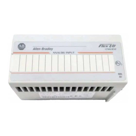
Summary of Contents for Allen-Bradley 1794-IE8XOE4
-
Page 1: Table Of Contents
Installation Instructions FLEX I/O DC Input, Output, and Input/Output Analog Modules Catalog Numbers 1794-IE12, 1794-OE12, and 1794-IE8XOE4 Table of Contents Topic Page Important User Information Environment and Enclosure Prevent Electrostatic Discharge North American Hazardous Location Approval Install Your Analog Input/Output Module... -
Page 2: Important User Information
2 FLEX I/O DC Input, Output, and Input/Output Analog Modules Important User Information Solid state equipment has operational characteristics differing from those of electromechanical equipment Safety Guidelines for the Application, Installation and Maintenance of Solid State Controls (Publication SGI-1.1 available from your local Rockwell Automation sales office or online at http://literature.rockwellautomation.com) describes some important differences between solid state equipment and hard-wired electromechanical devices. -
Page 3: Environment And Enclosure
Also, see the appropriate sections in this publication, as well as Industrial Automation Wiring and Grounding Guidelines, Allen-Bradley publication 1770-IN041, for additional installation requirements pertaining to this equipment. - Page 4 4 FLEX I/O DC Input, Output, and Input/Output Analog Modules WARNING: If you insert or remove the module while backplane power is on, an electrical arc can occur. This could cause an explosion in hazardous location installations. Be sure that power is removed or the area is nonhazardous before proceeding.
-
Page 5: North American Hazardous Location Approval
FLEX I/O DC Input, Output, and Input/Output Analog Modules North American Hazardous Location Approval The following information applies when Informations sur l’utilisation de cet équipement operating this equipment in hazardous en environnements dangereux: locations: Products marked CL I, DIV 2, GP A, B, C, D are suitable for Les produits marqués CL I, DIV 2, GP A, B, C, D ne conviennent use in Class I Division 2 Groups A, B, C, D, hazardous qu’à... -
Page 6: Install Your Analog Input/Output Module
These modules mount on a 1794-TB3G or 1794-TB3GS terminal base. 1. Rotate the keyswitch (1) on the terminal base (2) clockwise to position 3 (1794-IE12), 4 (1794-OE12), or 5 (1794-IE8XOE4) as required. 2. Make certain the FLEXBus connector (3) is pushed all the way to the left to connect with the neighboring terminal base/adapter. -
Page 7: Connect Wiring
FLEX I/O DC Input, Output, and Input/Output Analog Modules Connect Wiring Connect the wiring for the 1794-TB3G and 1794-TB3GS terminal bases as shown in the following figure: Terminal Base Wiring for the 1794-IE12/A Analog Input Module Chassis Chassis C0 C1... - Page 8 8 FLEX I/O DC Input, Output, and Input/Output Analog Modules Wire Connections for the 1794-IE12/A Analog Input Module Channel Signal Label 1794-TB3G or 1794-TB3GS Type Marking Input Common Terminal Input 0 Current B-17 Voltage Input 1 Current B-18 Voltage Input 2...
- Page 9 FLEX I/O DC Input, Output, and Input/Output Analog Modules Wire Connections for the 1794-OE12/A Analog Output Module Channel Signal Type Label 1794-TB3G or 1794-TB3GS Marking Output Common Terminal Output 0 Current B-17 Voltage Output 1 Current B-18 Voltage Output 2 Current B-23 Voltage...
- Page 10 10 FLEX I/O DC Input, Output, and Input/Output Analog Modules Wire Connections for the 1794-IE8XOE4/A Analog 8 Input/4 Output Module Channel Signal Type Label 1794-TB3G or 1794-TB3GS Marking Output Common Terminal Output 0 Current B-17 Voltage Output 1 Current B-18 Voltage Output 2 Current...
-
Page 11: Configuring Your Module
FLEX I/O DC Input, Output, and Input/Output Analog Modules Configuring Your Module You configure your output/input module by setting bits in the configuration word. Data Table – 1794-IE12 Dec. Oct. Read Words 0 - Input 0 Signed 2’s Complement data Value of Channel 0 1 - Input 1 Signed 2’s Complement data Value of Channel 1... - Page 12 12 FLEX I/O DC Input, Output, and Input/Output Analog Modules Range Selection Bits for the 1794-IE12, 1794-OE12, and 1794-IE8XOE4 Range Out of Range Range Setting Channel Configuration -10...+10V DC < -10.0V or > 10.0V Set bits for each C01 for channels 0 and 1...
-
Page 13: Data Table - 1794-Oe12
FLEX I/O DC Input, Output, and Input/Output Analog Modules Data Table – 1794-OE12 Dec. Oct. Read Words 0 - Status PU FP GF NU W11 W10 W9 W8 W7 W6 W5 W4 W3 W2 W1 W0 Write Words 0 - Reserved EN S1 S0 WR 0 1 - Output 0 Signed 2’s Complement data Value of Channel 0... -
Page 14: Data Table - 1794-Ie8Xoe4
14 FLEX I/O DC Input, Output, and Input/Output Analog Modules Data Table – 1794-IE8XOE4 Dec. Oct. Read Words 0 - Input 0 Signed 2’s Complement data Value of Channel 0 1 - Input 1 Signed 2’s Complement data Value of Channel 1 2 - Input 2 Signed 2’s Complement data Value of Channel 2 3 - Input 3... -
Page 15: Specifications
FLEX I/O DC Input, Output, and Input/Output Analog Modules Specifications General Specifications for the 1794-IE12, 1794-OE12, and 1794-IE8XOE4 Modules Attribute 1794-IE12 1794-OE12 1794-IE8XOE4 Indicators 1 red/green power/status indicator Recommended 1794-TB3G or 1794-TB3GS terminal base FLEXBus current 80 mA Power supply Voltage, nom.(nom) - Page 16 16 FLEX I/O DC Input, Output, and Input/Output Analog Modules Environmental Specifications Attribute 1794-IE12 1794-OE12 1794-IE8XOE4 Temperature, operating IEC 60068-2-1 (Test Ad, Operating Cold), IEC 60068-2-2 (Test Bd, Operating Dry Heat), IEC 60068-2-14 (Test Nb, Operating Thermal Shock): -20...60 °C (-4...140 °F)
- Page 17 0.004% full scale/°C 0...750 Ω Load on output current Load on voltage output, max 3.0 mA Includes offset, gain, nonlinearity, and repeatability error terms. Input Specifications – 1794-IE12 and 1794-IE8XOE4 Modules 1794-IE12 Attribute 1794-IE8XOE4 Number of inputs 12 single-ended, nonisolated...
- Page 18 18 FLEX I/O DC Input, Output, and Input/Output Analog Modules Input Specifications – 1794-IE12 and 1794-IE8XOE4 Modules 1794-IE12 Attribute 1794-IE8XOE4 Input voltage terminal +10V (user configurable) Input current terminal Specification 4...20 mA (user configurable) Certification 0...20 mA (user configurable) Input impedance, nom. (nom) Voltage terminal >...


Need help?
Do you have a question about the 1794-IE8XOE4 and is the answer not in the manual?
Questions and answers