Table of Contents
Advertisement
Advertisement
Table of Contents

Related Manuals for Raymarine M81131


Summary of Contents for Raymarine M81131
- Page 1 Linear Drive Installation Guide Drives covered: M81130 Type 1 Linear Drive 12 V M81131 Type 2 (short) Linear Drive 12 V M81132 Type 2 (long) Linear Drive 12 V M81133 Type 2 (short) Linear Drive 24 V M81134 Type 2 (long) Linear Drive 24 V...
-
Page 2: Safety Notices
EMC conformance All Raymarine equipment and accessories are designed to the best industry standards for use in the recreational marine environment. The design and manufacture of Raymarine equipment and accessories conform to the appropriate Electromagnetic Compatibility (EMC) standards, but correct installation is required to ensure that performance is not compromised. -
Page 3: Waste Electrical And Electronic Equipment Directive
Warranty To register your new Raymarine product, please take a few minutes to fill out the warranty card. It is important that you complete the owner information and return the card to receive full warranty benefits. Alternatively you can register your product at;... -
Page 4: Product Description
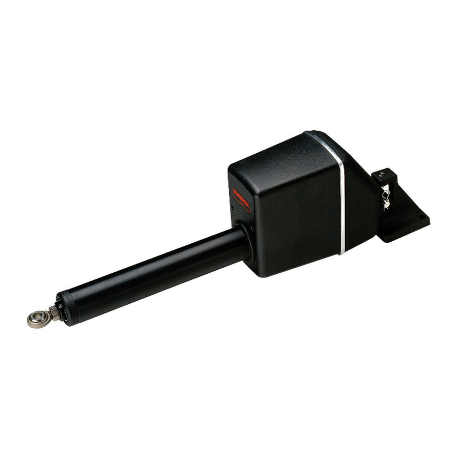
Introduction Product description Welcome to the installation guide for the Raymarine linear drive. This product is intended to operate the boat’s steering mechanism as part of a Raymarine autopilot system. It is designed for boats with existing mechanical steering systems. -
Page 5: Specifications
Drive specifications Table 1-1: Drive specifications Performance* Type 1 (T1) Type 2 short (T2S) Type 2 long (T2L) (at nominal voltage) M81130 (12 V) M81131 (12 V) M81132 (12 V) M81133 (24 V) M81134 (24 V) Maximum boat dis- 10,000 kg... -
Page 6: Drive Dimensions
Drive dimensions A (midstroke) 79 mm (3.1 in) 90º Drive Dimension 'A' 4 fixing holes suitable Type 1 700 mm (27.5 in) for 10 mm (0.4 in) bolts Type 2 (short) 700 mm (27.5 in) Type 2 (long) 850 mm (33.5 in) D5081-1 Figure 2: Linear drive dimensions Installation instructions... -
Page 7: Installation Steps
16 Complete the post-installation check. 1. EMC installation guidelines All Raymarine equipment and accessories are designed to the best industry standards for use in the recreational marine environment. Their design and manufacture conforms to the appropriate Electromagnetic Compatibility (EMC) standards, but correct installation is required to ensure that performance is not compromised. -
Page 8: Suppression Ferrites
Figure 3: Typical suppression ferrites Connections to other equipment If your Raymarine equipment is to be connected to other equipment using a cable not supplied by Raymarine, a suppression ferrite MUST always be attached to the cable near to the Raymarine unit. -
Page 9: Mounting The Drive
2. Mounting the drive Mounting the drive unit involves four main steps: • ensuring correct drive alignment • securing the drive to the boat • connecting the drive to the steering system • completing a steering check Drive alignment When mounting the linear drive unit, check that it is aligned correctly: Figure 4 •... -
Page 10: Securing The Drive
5º Max. 5º Max. D5078-1 Figure 5: Alignment between push rod and tiller arm plane of rotation Securing the drive Mounting location Before you secure the drive to your boat, you must first check the suitability of the mounting location. CAUTION Mounting location Consult the boat manufacturer if you have any doubt about the strength or... - Page 11 Securing bolts Attach the mounting foot with four stainless steel M10 ( inch) bolts and lock nuts/lock washers. Always mount the drive as securely as possible to make sure it performs reliably and remains cor- Note: rectly aligned. Connecting to the steering system CAUTION Equipment strength Consult the steering gear manufacturer if you have any doubt about the...
-
Page 12: Steering Check
R-clip Washer Rod end Flange Tiller arm Lock nut Lock washer Tiller pin Hole diameter 13 mm (0.52 in) D5076-1 Figure 6: Attaching the push rod to the tiller arm Steering check When you have mounted the drive unit, turn the boat’s steering wheel from hardover to hardover and check that: Figure 5 •... -
Page 13: Moving Parts
WARNING Moving parts Keep clear of moving steering systems at all times. Protect moving parts from access during normal use. 3. Connecting to the course computer WARNING Electrical safety Make sure the power supply is switched OFF before you make any electrical connections. -
Page 14: Post-Installation Checklist
– – – – – – POWER MOTOR lk CLUTCH POWER MOTOR SOLENOID CLUTCH SWITCH Type 150/400 course computer Type 100/300 course computer D5080-1 Figure 8: Cable connections at course computer Table 1-1: Recommended cable sizes Cable length Cable gauge Copper area (drive unit to course computer) (AWG) -
Page 15: Maintenance
• Ensure that cables have no signs of wear or damage. • Check for unusual noisy operation, such as clicking or grinding noises, or unusual vibra- tion. If any of these are detected, the drive must be taken to a Raymarine authorized ser- vice representative before further use. -
Page 16: Product Support
• Always report any EMC-related problem to your nearest Raymarine dealer. We use such information to improve our quality standards. • In some installations, it may not be possible to prevent the equipment from being affected by external influences. In general this will not damage the equipment but it can lead to spurious resetting action, or momentarily may result in faulty operation.
Need help?
Do you have a question about the M81131 and is the answer not in the manual?
Questions and answers