Table of Contents
Advertisement
Available languages
Available languages
Quick Links
Download this manual
See also:
User Manual
Advertisement
Chapters
Table of Contents

Related Manuals for ZENEC ZE-MR1502


Summary of Contents for ZENEC ZE-MR1502
- Page 1 MODEL NO: ZE-MR1 502 15.4"/16:9 ROOF MOUNT LCD MONITOR INSTRUCTION MANUAL...
- Page 2 ZE-MR1502 Vielen Dank für den Kauf dieses ZENEC-Produktes! Mit dem Kauf des ZE-MR1502 haben Sie sich für ein technisch ausgereiftes Produkt entschieden, das Ihnen durch die Verwendung von hochwertigen Materialien und Bauteilen eine lange Lebensdauer garantiert. Bei dem ZE-MR1502 von ZENEC handelt es sich um einen 15.4"/16:9 TFT-LCD Aktiv-Matrix Deckenmonitor.
-
Page 3: Table Of Contents
DEUTSCH LIEFERUMFANG Abbildung Element Menge Deckenmonitor IR-Fernbedienung inkl. Batterie A/V-Interface Montageplatte ST4.2×16 Schrauben Abdeckungen CM4x8 Schrauben Bedienungsanleitung 1A Sicherung Distanzgummi INHALTSVERZEICHNIS SICHERHEITSHINWEISE ..................... 4 DIE FERNBEDIENUNG ....................5 DIE EINZELNEN TASTEN .................... 5 BENUTZEN DER FERNBEDIENUNG ................. 5 DIE BATTERIE ......................6 BITTE BEACHTEN ....................... -
Page 4: Sicherheitshinweise
Sie die defekte Sicherung gegen ein neues Exemplar mit identischen Werten austauschen. Sollte der Kurzschluss immer noch vorhanden sein, wenden Sie sich bitte an Ihren ZENEC-Händler. 6. Achten Sie bei der Installation des Monitors darauf, dass er den Fahrer des Fahrzeuges nicht vom Verkehrsgeschehen ablenkt oder ihm in irgendeiner Weise die Sicht versperrt. -
Page 5: Die Fernbedienung
Gegenstände die ebenfalls mit der LCD-Flüssigkeit in Kontakt gekommen sind, sollten sorgfältig mit Wasser gereinigt werden. 13. Wenn Sie Fragen oder Probleme bei der Installation haben, wenden Sie sich bitte an einen ZENEC-Händler oder an den jeweiligen Landesvertrieb. DIE FERNBEDIENUNG DIE EINZELNEN TASTEN ➀... -
Page 6: Die Batterie
DIE BATTERIE ■ Wenn die Fernbedienung nicht oder sehr langsam reagiert, müssen Sie wahrscheinlich die Batterie wechseln: 1. Öffnen Sie den Batteriefachdeckel, indem Sie die Halterung 1. nach rechts drücken und den Batterie- ziehen fachdeckel anschließend nach vorne ziehen (siehe Skizze). -
Page 7: Der Deckenmonitor
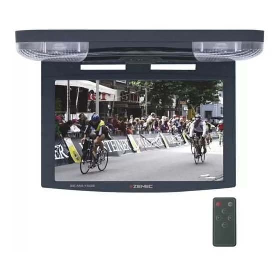
DEUTSCH DER DECKENMONITOR DIE EINZELNEN TASTEN 6 6 3 5 4 3 2 1 1. [POWER]-Taste ■ Drücken Sie die [POWER]-Taste um das Gerät ein- bzw. auszuschalten. 2. [MODE]-Taste ■ Drücken Sie die [MODE]-Taste um zwischen den beiden A/V-Eingängen A/V-1 und A/V-2 zu wählen. -
Page 8: Öffnen Und Schliessen Des Deckenmonitors
ÖFFNEN UND SCHLIESSEN DES DECKENMONITORS 1. ÖFFNEN DES DECKENMONITORS Drücken Sie die [OPEN]-Taste um das Display des Deckenmonitors zu öffnen und stellen Sie von Hand den gewünschten Winkel des Displays ein. BITTE BEACHTEN Der Winkel des Displays lässt sich bis zu maximal 150° einstellen. ■... -
Page 9: Menüeinstellungen
DEUTSCH MENÜEINSTELLUNGEN ■ Drücken Sie eine der [MENU]-Tasten um das Menü aufzurufen. ■ Durch wiederholtes Drücken der Tasten können Sie den Menüpunkt auswählen, welchen Sie verändern möchten. ■ Drücken Sie die [UP/DOWN]-Taste am Gerät oder die [VOLUMEN +/–]-Tasten auf der Fernbedienung, um den jeweiligen Wert entsprechend zu verändern. -
Page 10: Installation Des Gerätes
INSTALLATION DES GERÄTES A/V-1 A/V-2 Gelb: 12V Rot: ACC Schwarz: GND Ausgang Rot: Türkontakt Gelb: 12V Schwarz: GND... -
Page 11: Anschluss Der Innenraumbeleuchtung
DEUTSCH ANSCHLUSS DER INNENRAUMBELEUCHTUNG Positiv geschaltetes System Gelb: 12V Schwarz: GND Rot: Türkontakt Schaltkreis der auftrennen originalen Innenraumbeleuchtung Negativ geschaltetes System Gelb: 12V Schwarz: GND Rot: Türkontakt Schaltkreis der auftrennen originalen Innenraumbeleuchtung... -
Page 12: Montage Des Gerätes
MONTAGE DES GERÄTES Schritt 1: Befestigen Sie die Montageplatte unter Berücksichtigung der richtigen Schraubenlänge ■ (Lieferumfang ST 4.2x16) am Dach Ihres Fahrzeuges (siehe folgende Skizze). Beachten Sie dass die Öffnung der originalen Innenraumbeleuchtung durch die Montageplatte nicht verdeckt wird. Dach des Fahrzeuges Montageplatte Schrauben ST4.2x16 *8... - Page 13 DEUTSCH Dach des Fahrzeuges Distanzgummi Montageplatte Monitor CM 4x8 Schrauben *8 Abdeckungen *8 Schritt 7: Überprüfen Sie noch einmal die Installation und alle Funktionen des Gerätes. ■...
-
Page 14: Fehlersuche
Fernbedienung ist leer. Batterie in die Fernbedienung ein. 2. Die Fernbedienung ist defekt. 2. Wenden Sie sich an einen ZENEC-Händler um die Fernbedienung auszutauschen. Das Bild ist zu dunkel. 1. Die Umgebungs- 1. Dieser Effekt ist typisch für temperatur ist zu niedrig. -
Page 15: Spezifikationen
DEUTSCH SPEZIFIKATIONEN Spannungsversorgung: +10.5V − +16V (DC) Mechanismus: Manuell Kippwinkel: < 150° Stromverbrauch: < 1.2A (Beleuchtung aus) Beleuchtung: 2 x 5W Betriebstemparatur: -20° C bis +75° C Lagertemparatur: -40° C bis +85° C Abmessungen (mm): 384 x 340 x 47 (H x B x T) Gewicht (g): 2290 ■... - Page 16 This monitor is compatible with PAL and NTSC video streams – the internal video signal processing electronics automatically synchronize with PAL or NTSC video signals. Applications: The ZE-MR1502 will work in combination with any common video source unit, featuring an RCA composite video output, such as DVD-players, VCR’s or TV-tuners.
- Page 17 ENGLISH BOX CONTENTS Appearance Parts Neme Quantity LCD Monitor IR Remote Control w/Battery A/V-Interface Metal Mounting Plate ST4.2×16 Screw Adhesive foam CM4x8 Screw User’s Manual 1A Fuse Rubber Spacer CONTENT SAFETY INFORMATION .................... 18 REMOTE CONTROL ....................19 REMOTE CONTROL FUNCTIONS ................19 USING THE REMOTE CONTROL ................
-
Page 18: Safety Information
SAFETY INFORMATION 1. The unit is designed for using with a DC +12V, negative ground battery power supply, it may not be connected and/or used differently. 2. Do not operate the unit in any way other than described in this manual. Failure to follow the instructions will invalidate your warranty. -
Page 19: Remote Control
ENGLISH 13. Do not drop or hit the LCD panel with hard objects, as it may cause permanent damage to the unit. If you come into contact with any spilled LCD fluid, wash and clean affected areas with plenty of water and soap and seek medical attention immediately. 14. -
Page 20: Battery
BATTERY ■ Please remove the insulation plastic sheet insert from the battery holder before use. ■ If the remote control does not function correctly or the operating range is reduced, replace the battery with a new battery (CR2025). 1. Apply pressure on the recess of the battery tray on the Pull back of remote control with a small tool. -
Page 21: The Roof Mount Monitor
ENGLISH THE ROOF MOUNT MONITOR BASIC OPERATIONS 6 6 3 5 4 3 2 1 1. POWER ■ Press the POWER button to switch on / off the unit. 2. MODE ■ Select input signal AV 1 or AV 2 with MODE button. 3. -
Page 22: Lcd Panel Adjustment
LCD PANEL ADJUSTMENT 1. OPEN THE LCD PANEL Press Open Button to disengage the LCD panel. Pull the LCD panel outward till you reach the desired viewing angle. NOTE ■ The LCD display opens to a maximum angle of 150° degrees. Opening it further than that may cause damages. -
Page 23: Menu
ENGLISH MENU ■ To adjust the picture, use the menu button to select the menu features you would like to adjust. ■ The values of selected feature can be adjusted by pressing the “+” and “–” button on the remote control or “5” and “6” button on the panel. CONTRAST: Contrast adjustment Operation Menu BRIGHTNESS: Brightness setting... -
Page 24: Electrical Connections
ELECTRICAL CONNECTIONS A/V-1 A/V-2 Yellow: 12V Red: ACC Black: GND OUTPUT Red: Door Switch Yellow: Car Battery Black: Common... -
Page 25: Built-In Dome Light
ENGLISH BUILT-IN DOME LIGHT... -
Page 26: Installation
INSTALLATION Step 1: ■ Select the screw from ST4.2X16 by length that applies to your vehicle, contained in the package contents. Screw the metal mounting plate to the car roof. Please remember not to cover the opening of original dome light. Car Roof Metal Plate Screw... - Page 27 ENGLISH Car Roof Rubber Spacer Metal Plate Monitor CM 4x8 Screw *8 Adhesive foam *4 Step 7: ■ Please double check and make sure the unit is installed properly before operation.
-
Page 28: Troubleshooting
TROUBLESHOOTING Cause Solution Problem: No picture when the 1. Power wire is 1. Check the power wire display is turned on. connected improperly and replace the fuse. or fuse blown. 2. Check system cable or 2. System cable is not replace with a new one. -
Page 29: Specifications
ENGLISH SPECIFICATIONS Operating Voltage Range: Car Battery (DC +10.5V ~ +16V) Mechanism: Manual Open / Close Display Angle: Vertical Adjustable: Up/Down < 150° Operating Current: < 1.2A (Dome Light Off) Dome Light: 5W x 2 Operating Temperature: -20° C to +75° C Storage Temperature: -40°... -
Page 30: Garantie
2 YEARS LIMITED WARRANTY Dear customer Thank you for purchasing this ZENEC product. It is advisable to keep the original packing material for any future transporting of the product. Should your ZENEC product require warranty service, please return it to the retailer from whom it was purchased or the distributor in your country. - Page 31 WARRANTY/GARANTIE ZENEC MODEL: ZE-MR1502 Serial Number:..........................Date of Purchase: ......................... Your name: ........................... Your address: ..........................City: .............................. State: ........ZIP or Postal Code ................ Country: ............................Dealer’s address & stamp...
Need help?
Do you have a question about the ZE-MR1502 and is the answer not in the manual?
Questions and answers