Advertisement
Quick Links
ELECTRONICS
© Samsung Electronics Co., Ltd. NOV. 2000
Printed in Korea
AC68-01289A
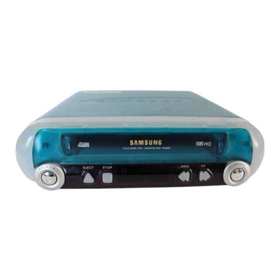
VIDEO CASSETTE RECORDER
VR400G/400P
VR400PC/400RC
SV-400GP/400PP/400RP
SV-400GUP/400PUP/400RUP
SV-400GUM/400PUM/400RUM
SERVICE
For mechanical disassembly and adjustment, refer to the "Mechanical Manual" (DX-9R
VIDEO CASSETTE RECORDER
EJECT
STOP
REW
F.F
Manual
AC68-00001A).
CONTENTS
1. Precautions
2. Alignment and Adjustment
3. Exploded View and Parts List
4. Electrical Parts List
5. Schematic Diagrams
Advertisement

Summarization of Contents
Important Service Guide
Mode Switch Assembly Point
Instructions for aligning the mode switch assembly point when installing the full deck.
How to Eject Cassette Tape
Procedure for manually ejecting a cassette tape when the unit does not operate.
Precautions
Leakage Current Hot Check
Procedure for performing a leakage current hot check using a leakage current tester.
X-ray Limits
Information regarding X-ray emission limits and picture tube replacement.
Antenna Cold Check
Procedure for performing an antenna cold check using an ohmmeter.
High Voltage Limit
Importance of measuring and adhering to high voltage limits during servicing.
Static Electricity Sensitivity
Handling precautions for electrostatic sensitive devices (ESDs) to prevent damage.
Design Alteration Warning
Warning against altering the mechanical or electrical design of the unit.
Hot Chassis Warning
Safety precautions for servicing hot chassis units connected to the AC power cord.
Picture Tube Implosion Warning
Warning regarding picture tube implosion protection during handling and replacement.
Product Safety Notice
Importance of using identical replacement parts for safety characteristics.
Alignment and Adjustment
Reference for Adjustments
Overview of adjustable items like X-Point, Head Switching, and NVRAM settings.
Remote Control Adjustment Buttons
Identification of buttons on the remote control used for adjustments.
Test Point for Adjustment Mode
Location of test points on the Main PCB for setting adjustment modes.
ACE Head Position (X-Point) Adjustment
Procedure for adjusting the ACE head position (X-Point).
Head Switching Point Adjustment
Procedure for adjusting the head switching point.
NVRAM Option Setting
Procedure for setting NVRAM options after component replacement.
Exploded View and Parts List
Cabinet Assembly
Exploded view of the cabinet assembly and its components.
Mechanical Parts (Top Side)
Exploded view of mechanical parts on the top side of the unit.
Mechanical Parts (Bottom Side)
Exploded view of mechanical parts on the bottom side of the unit.
Schematic Diagrams
Block Identification of Main PCB
Block diagrams illustrating the main functional areas of the Main PCB.
S.M.P.S. (120 Voltage) Schematic
Schematic diagram for the 120V Switching Mode Power Supply (SMPS) section.
S.M.P.S. (Free Voltage) Schematic
Schematic diagram for the free voltage Switching Mode Power Supply (SMPS) section.
Power Schematic
Schematic diagram for the power supply circuits.
Logic Schematic
Schematic diagram for the logic control circuits.
Audio/Video Schematic
Schematic diagram for the audio and video processing circuits.
TM-Block/Input-Output Schematic
Schematic diagram for the TM-Block and input/output interfaces.
Display Schematic
Schematic diagram for the display and front panel interface.
Disassembly and Reassembly
Deck Parts Identification
Identifies key parts in the top and bottom views of the VHS deck.
Main Deck Component Removal
Procedures for removing main deck components like brackets, levers, and drives.
Cassette Mechanism Disassembly
Procedures for removing cassette holder, arm, and related mechanisms.
Gear and Motor Assembly Removal
Procedures for removing gear assemblies, motors, and worm mechanisms.
Tension and Brake System Removal
Procedures for removing tension, brake, and sleeve assemblies.
Reel and Clutch Assembly Removal
Procedures for removing reel disks and clutch assemblies.
Head and Pinch Roller Assembly Removal
Procedures for removing heads, pinch rollers, and guide assemblies.
Cylinder and Pulley Assembly Removal
Procedures for removing cylinder, pulley, and motor capstan assemblies.
Manual Cassette Ejection
Manual procedure for ejecting a cassette if the unit is inoperative.
Alignment and Adjustment
Tape Transport System Adjustment Locations
Overview of tape transport system components and adjustment points.
ACE Head Assembly Adjustment
Procedures for adjusting ACE head height, tilt, azimuth, and position.
Linearity Adjustment (Guide Roller S, T)
Procedure for adjusting guide rollers S and T for linearity.
Transitional Operation Check (RPS to Play)
Procedure to check transitional operation from RPS to Play mode.
Envelope Check
Procedure for checking playback output envelope specifications.
Tape Wrinkle Check
Procedure for checking and correcting tape wrinkles at various guides.
Reel Torque
Information on reel torque specifications and measurement.
Tension Post Adjustment
Procedure for adjusting the tension post and confirming back tension.


Need help?
Do you have a question about the VR400G and is the answer not in the manual?
Questions and answers