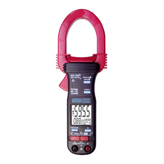
Table of Contents
Advertisement
Quick Links
Advertisement
Table of Contents

Summarization of Contents
SAFETY
Meter Protection Rating
Details meter protection rating and relevant standards for safety.
Measurement Categories
Defines CAT IV, CAT III, and CAT II for different installation types.
Terms in Manual
Explains the meaning of WARNING and CAUTION terms used in the manual.
OPERATIONAL SAFETY WARNINGS
General Safety Precautions
Avoid rain/moisture, use indoors, observe high voltage precautions, inspect leads.
Hand/Finger Barrier Use
Keep hands behind safety barriers during measurements.
Live Conductor Handling
Meter for uninsulated live conductors; PPE advised.
CAUTIONARY NOTES
Function Change Safety
Disconnect test leads before changing meter functions.
INTERNATIONAL ELECTRICAL SYMBOLS
Symbol Explanations
Covers Caution, Electric Shock, Earth, Double Insulation, Fuse, AC, DC, Live Conductor symbols.
CENELEC DIRECTIVES
Compliance Statement
States compliance with CENELEC Low-voltage and EMC directives.
PRODUCT DESCRIPTION
Clamp Jaws & Markings
Explains clamp jaws, marking lines for ACA/Power position error.
Controls and Display
Details push-buttons, input jacks, slide-switch, and LCD display.
Jaw Operation
Describes the jaw trigger and center indicators for accuracy.
OPERATION BASICS
Pre-Measurement Safety Check
Test voltage function on a known source before use.
AutoVATM Functionality
Automatic ACV, DCV, or ACA selection based on input.
Auto-VA Operation
How the meter selects functions and manual override.
Clamp-on Meter Caution
Safe application/removal for non-invasive current measurements.
MEASUREMENT TECHNIQUES
Conductor Measurement
Clamp around single conductor; avoid multiple for differential current.
Accuracy Considerations
Position conductor at jaw center; minimize adjacent device influence.
TOTAL HARMONIC DISTORTION (THD%-F)
THD%-F Formula & Interpretation
Formula and meaning for sinusoidal/distorted waveforms.
THD%-F Display Control
Toggling between main and secondary display readings.
ADVANCED FUNCTIONS
Line-level Frequency
Activating and using the frequency measurement function.
Peak-rms Mode
Measuring surge voltage/current with short durations.
HOLD Mode
Freezing the display for later viewing.
APO Disable for Peak-rms
Note on disabling Auto Power Off for long-term Peak-rms use.
POWER FACTOR CONCEPTS
Power Introduction
Rate of energy change, instantaneous and average power.
Displacement Power Factor (DPF)
DPF for sinusoidal waveforms.
Total Power Factor (TPF)
TPF considering harmonics.
Power Factor Improvement
Addressing harmonics before phase-shift.
POWER MEASUREMENT
Power Function Setup
Setting the slide-switch to the Power position.
Power Measurement Selection
Choosing between W, VAR, or VA.
POWER FACTOR DISPLAY & INDICATION
PF Display
Total Power Factor shown in secondary mini display.
'A-lags' and Capacitive Indication
Explains inductive vs. capacitive circuit indicators.
Power Reading Interpretation
Guidance on positive/negative Real Power readings.
Harmonics & 'A-lags' Note
Effect of harmonics on 'A-lags' detection.
SINGLE PHASE POWER MEASUREMENT
Single Phase Measurement Examples
Illustrates kW, kVA, and VAR measurements with PF.
3-PHASE 4-WIRE (3~4W) POWER MEASUREMENT
3-Phase 4-Wire Setup
Using clamp meters for phase-to-neutral powers.
Total Power Calculation (3~4W)
Formulas for unbalanced and balanced loads.
3-PHASE 3-WIRE (3~3W) POWER MEASUREMENT
3-Phase 3-Wire Setup
Using clamp meters for two power components.
Total Power Calculation (3~3W)
Formulas for unbalanced and balanced loads.
TEMPERATURE MEASUREMENT (MODELS 152 & 155)
Temperature Setup & Units
Using Type-K probes and switching °C/°F.
OHM AND CONTINUITY FUNCTIONS
Ohm/Continuity Setup
Selector position and function toggling.
DISPLAY AND POWER FEATURES
Backlight Control
Turning the display backlight on or off.
Auto Power Off (APO)
Meter powers off automatically; waking from APO.
ADVANCED FEATURE CONTROL
Disabling Auto-Power-Off (APO)
Procedure to disable APO.
PC Computer Interface
Requirements and activation for data output.
MAINTENANCE AND TROUBLESHOOTING
Maintenance Safety Warning
Disconnect power before opening.
Troubleshooting Guide
Basic steps for operational failures.
Voltage Transient Protection
Protection mechanism and repair needs.
CLEANING AND BATTERY MANAGEMENT
Cleaning and Storage
Wiping with damp cloth; battery removal for long-term storage.
Battery Replacement
Type, steps, and recommendations.
GENERAL SPECIFICATIONS OVERVIEW
Display Capabilities
Counts for Voltage, Power/Ohm/Hz, ACA clamp.
Update Rates
Nominal update rate for Power function.
DETAILED SPECIFICATIONS
Update Rates & Polarity
Other function update rates and automatic polarity.
Environmental & Operating Conditions
Temp, Humidity, Altitude, Storage.
Safety & EMC Standards
Compliance with IEC, EN, UL, CAN/CSA, EMC directives.
Measurement Category & Transient Protection
CAT III 600V and 6.5kV protection.
Overload Protections
Limits for ACA jaws and input terminals.
Power Supply & Consumption
Battery type, power usage by function, APO consumption.
Dimensions & Weight
Physical size and weight of meter models.
Jaw Opening Capacity
Max conductor diameter for jaw opening.
SPECIAL FEATURES AND ACCESSORIES
Key Special Features
Backlight, AutoVATM, Power Measurement, THD%-F, PEAK-rms HOLD.
Included Accessories
Standard items provided with the meter.
Optional Accessories
PC interface kit and plug adapter.
ELECTRICAL SPECIFICATIONS & ACCURACY
General Accuracy Statement
Definition and conditions for accuracy.
AC Voltage Accuracy
Accuracy across different frequency ranges.
Input Impedance & Crest Factor
ACV input impedance and crest factor limits.
AutoVATM & PEAK-rms HOLD
Thresholds and response times.
DETAILED ELECTRICAL SPECIFICATIONS
DC Voltage & Ohms Accuracy
Specifications for DCV and Ohm measurements.
Continuity Tester
Threshold and response time for continuity testing.
ACA Current Accuracy
Accuracy for ACA clamp-on measurements.
ACA AutoVA™ Threshold & Crest Factor
Thresholds and crest factor limits for ACA.
ACA Induced Error
Error from adjacent conductors.
Accuracy Notes
Clarifications on range, position, and induced errors.
ADVANCED SPECIFICATIONS AND ACCURACY
Position Error Adjustments
Accuracy adjustments for measurements within/beyond jaw lines.
Temperature Accuracy
Specifications and adjustments for temperature readings.
Frequency Accuracy & Sensitivity
Specifications for frequency measurements.
THD%-F Accuracy (Model 155)
Accuracy by harmonic order and conditions.
THD%-F Definitions & Settings
Formula, range, resolution, and accuracy adjustments.
POWER FACTOR AND POWER MEASUREMENT ACCURACY
Total Power Factor (PF) Accuracy
Accuracy for PF measurement range.
Power (kVA/kW/kVAR) Accuracy
Accuracy tables for power measurements.
Power Accuracy Conditions
Conditions affecting power measurement accuracy.
'A-lags' Indication Conditions
Specific conditions for 'A-lags' indication.
LIMITED WARRANTY INFORMATION
Warranty Coverage & Exclusions
Terms, duration, and excluded items.
Obtaining Service & BRYMEN's Obligation
How to get service and BRYMEN's responsibilities.
Warranty Disclaimer & Liability Limitation
Legal disclaimers and liability limits.


Need help?
Do you have a question about the PowerClamp BM155 and is the answer not in the manual?
Questions and answers