Table of Contents
Advertisement
Quick Links
Advertisement
Table of Contents

Subscribe to Our Youtube Channel
Related Manuals for Brymen PowerClamp BM151


Summary of Contents for Brymen PowerClamp BM151
- Page 1 USER'S MANUAL BM151, BM152, BM155, & BM351 PowerClamp Series...
-
Page 2: Terms In This Manual
1) SAFETY This manual contains information and warnings that must be followed for operating the instrument safely and maintaining the instrument in a safe operating condition. If the instrument is used in a manner not specified by the manufacturer, the protection provided by the instrument may be impaired. -
Page 3: International Electrical Symbols
WARNING To reduce the risk of fire or electric shock, do not expose this product to rain or moisture. The meter is intended only for indoor use. To avoid electrical shock hazard, observe the proper safety precautions when working with voltages above 60 VDC or 30 VAC rms. These voltage levels pose a potential shock hazard to the user. -
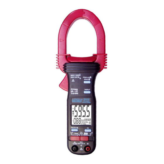
Page 4: Product Description
3) PRODUCT DESCRIPTION Note: Top of the line model is used as representative for illustration purposes. Please refer to your respective model for function availability. 1) Transformer Clamp Jaws for AC current magnetic field pick up 2) Jaw marking lines for ACA (& thus Power) position error indication 3) Hand/Finger Barrier to indicate the limits of safe access to the jaws... -
Page 5: Operation
4) OPERATION CAUTION: Before and after hazardous voltage measurements, test the voltage function on a known source such as line voltage to determine proper meter functioning. AutoVA function Set the slide-switch function-selector to the position. ●With no input, the meter displays “Auto” when it is ready. ●With no ACA current input via the jaws but a voltage signal above the nominal threshold of DC 2.4V or AC 30V (40Hz ~ 500Hz) up to the rated 600V is present on V-COM terminals, the meter displays the voltage value in appropriate DC or AC,... - Page 6 jaws around only one single conductor of a circuit for load current measurement. Make sure the jaws are completely closed, or else it will introduce measurement errors. Enclosing more than one conductor of a circuit will result in differential current measurement (like identifying leakage current).
- Page 7 Line-level Frequency function When ACV or ACA function is auto-selected or manual-selected, press Hz button momentarily toggles to Line-level Frequency function. Frequency trigger levels vary automatically with function ranges. Peak-rms mode Peak-rms compares and displays the maximum RMS value of surge voltage or current with durations as short as 65ms.
- Page 8 Notes on Displacement Power Factor & Total Power Factor ●Introduction: Power is the rate of change of energy with respect to time (in terms of voltage V and current A). Instantaneous (real) power w = vi where v is the instantaneous voltage and i the instantaneous current.
- Page 9 ●PF (Total Power Factor) displays simultaneously in the secondary mini display. Denoting efficiency, absolute PF value is adopted. ●“A-lags” LCD annunciator turns on to indicate an inductive circuit, or Current A lags Voltage V (i.e., phase-shift angle θ is “+”). On the contrary, together with significant PF values, WITHOUT turning on “A-lags”...
- Page 10 ●Measuring 3-Phase 4-Wire (3 4W) Power Parameters: In both un-balanced and balanced load cases, 3-Phase 4-Wire (3 4W) systems, measure the phase-to-neutral powers kW and kW of each phase separately as illustrated. System (total) power kW is the summation of all three phase-to-neutral Total powers.
- Page 11 ●Measuring 3-Phase 3-Wire (3 3W) Power Parameters: In both un-balanced and balanced load cases, 3-Phase 3-Wire (3 3W) systems, measure the power components kW and kW separately as illustrated. System (total) power kW is the summation of the two measured power components. That is: Total = kW + kW...
- Page 12 Temperature function (model 152 & 155 only) Set the slide-switch function-selector to the F position. Default at last selected function. Press SELECT button to toggle between C and F measurement functions. Be sure to insert the banana-plug type-K temperature bead probe Bkp60 at correct polarities.
-
Page 13: Maintenance Warning
Disabling Auto-Power-Off (APO) Press-and-hold the HOLD button while sliding the function-selector to a (designated) function-selector position. This disables the Auto-Power-Off feature of the functions on that particular function-selector position. The LCD displays “ ” & “ ” to confirm activation right after the HOLD button is released. Slide the function-selector to any other positions will then resume Auto-Power-Off feature. - Page 14 Cleaning and Storage Periodically wipe the case with a damp cloth and mild detergent; do not use abrasives or solvents. If the meter is not to be used for periods of longer than 60 days, remove the batteries and store them separately Battery replacement The meter uses standard 1.5V AAA Size (NEDA 24A or IEC LR03) battery X 2 Loosen the 2 captive screws from the battery cover case.
- Page 15 Voltage, ACA clamp-on, Ohm, Hz & Temperature functions: 4 per second nominal Polarity : Automatic Low Battery : Below approx. 2.4V Operating Temperature : 0 C to 40 Relative Humidity : Maximum relative humidity 80% for temperature up to 31 decreasing linearly to 50% relative humidity at 40 Altitude : Operating below 2000m Storage Temperature : -20...
- Page 16 Special features : Backlight display (model 152 & 155 only); AutoVA (Auto Selection on ACV, DCV or ACA functions); Power measurement of selectable W, VAR & VA with dual-display Total Power Factor features; Total harmonic distortion THD%-F (model 155 only); PEAK-rms HOLD Accessories : Test leads (pair), batteries installed, user's manual, soft carrying pouch, &...
- Page 17 DC Voltage Accuracy RANGE 600.0V 0.5% + 5d Input Impedance: 2MΩ, 30pF nominal DCV AutoVA Threshold: 2.4VDC nominal Ohms RANGE Accuracy 1.0% + 6d 999.9Ω Open Circuit Voltage : 0.4VDC typical Audible Continuity Tester Audible threshold: between 10Ω and 300Ω. Response time: 250µs ACA Current (Clamp-on) 1) 2)
- Page 18 errors introduced are: Add 1% to specified accuracy for measurements made WITHIN jaw marking lines (away from jaw opening) Add 4% to specified accuracy for measurements made BEYOND jaw marking lines (toward jaws opening) Temperature (model 152 & 155 only) RANGE Accuracy C ~ 300...
- Page 19 Total Power Factor (PF) RANGE Accuracy 0.10 ~ 0.99 F ~ 21st 22nd ~ 51st Specified accuracy @ ACA fundamental > 2A ; ACV fundamental > 50V Power RANGE Accuracy 1) 2) 0 ~ 600.0 F ~ 10th 11th ~ 46th 47th ~ 51st @ PF = 0.99 ~ 0.1 2.0%+6d...
-
Page 20: Limited Warranty
BRYMEN's warranty does not apply to accessories, fuses, fusible resistors, spark gaps, batteries or any product which, in BRYMEN's opinion, has been misused, altered, neglected, or damaged by accident or abnormal conditions of operation or handling.
Need help?
Do you have a question about the PowerClamp BM151 and is the answer not in the manual?
Questions and answers