Denon AVR-2105 Operating Instructions Manual
Denon av surround receiver operating instructions
Hide thumbs
Also See for AVR-2105:
- Operating instructions manual (296 pages) ,
- Service manual (263 pages) ,
- Specifications (2 pages)
Table of Contents
Advertisement
AV SURROUND RECEIVER
RÉCEPTEUR AUDIO-VIDÉO
AVR-2105/885
OPERATING INSTRUCTIONS
MODE D'EMPLOI
FUNCTION
MAIN
SOURCE
ON / STANDBY
FOR ENGLISH READERS
PAGE 2 ~ PAGE
We greatly appreciate your purchase of this unit.
2
To be sure you take maximum advantage of all the
2
features this unit has to offer, read these instructions
carefully and use the set properly. Be sure to keep this
manual for future reference should any questions or
problems arise.
"SERIAL NO.
PLEASE RECORD UNIT SERIAL NUMBER ATTACHED TO
THE REAR OF THE CABINET FOR FUTURE REFERENCE"
SIGNAL
INPUT
DIGITAL
AUTO
PCM
INPUT MODE
ANALOG
EXT. IN
BAND
SHIFT
ª
PRESET
•
ZONE 2 /
REC SELECT
PHONES
SPEAKER
SURROUND
5CH / 7CH
DIRECT /
STANDARD
STEREO
STEREO
BACK
A
B
ON
OFF
73, 144 ~ 148
MASTER VOLUME
VOLUME LEVEL
OUTPUT
SURROUND
DTS
BACK
ZONE 2
ª
TUNING
•
VIDEO SELECT
DIMMER
STATUS
SELECT
SELECT
SURROUND
TONE
MODE
CONTROL
V.AUX INPUT
SURROUND
TONE
PARAMETER
DEFEAT
S-VIDEO
VIDEO
L
AUDIO
R
OPTICAL
SETUP MIC
AVR-2105
AV SURROUND RECEIVER
POUR LES LECTEURS FRANCAIS
Nous vous remercions pour l'achat de cet appareil.
2
Pour être sûr de profiter au maximum de toutes les
2
caractéristiques qu'offre cet appareil, lire avec soin ces
instructions et bien utiliser l'appareil. Toujours
conserver ce mode d'emploi pour s'y référer
ultérieurement en cas de question ou de problème.
"NO. DE SERIE
PRIERE DE NOTER LE NUMERO DE SERIE DE L'APPAREIL
INSCRIT A L'ARRIERE DU COFFRET DE FAÇON A POUVOIR
LE CONSULTER EN CAS DE PROBLEME."
PAGE 2, 74 ~ PAGE 148
Advertisement
Table of Contents

Related Manuals for Denon AVR-2105


Summary of Contents for Denon AVR-2105
-
Page 1: Operating Instructions
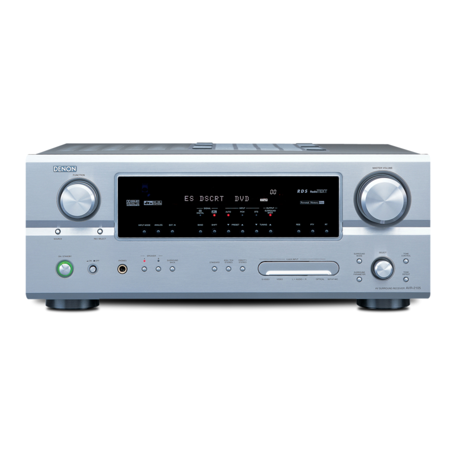
AV SURROUND RECEIVER RÉCEPTEUR AUDIO-VIDÉO AVR-2105/885 OPERATING INSTRUCTIONS MODE D’EMPLOI FUNCTION MAIN SOURCE ZONE 2 / REC SELECT ON / STANDBY PHONES FOR ENGLISH READERS PAGE 2 ~ PAGE We greatly appreciate your purchase of this unit. To be sure you take maximum advantage of all the features this unit has to offer, read these instructions carefully and use the set properly. -
Page 2: Safety Precautions
FCC requirements. Modification not expressly approved by QUALIFIED SERVICE DENON may void your authority, granted by the FCC, to use the product. 3. NOTE This product has been tested and found to comply with the limits for a Class B digital device, pursuant to Part 15 of the FCC Rules. -
Page 3: Safety Instructions
SAFETY INSTRUCTIONS Read Instructions – All the safety and operating instructions should be read before the product is operated. Retain Instructions – The safety and operating instructions should be retained for future reference. Heed Warnings – All warnings on the product and in the operating instructions should be adhered to. -
Page 4: Table Of Contents
INTRODUCTION Thank you for choosing the DENON AVR-2105/885 Digital A / V Surround Receiver. This remarkable component has been engineered to provide superb surround sound listening with home theater sources such as DVD, as well as providing outstanding high fidelity reproduction of your favorite music sources. -
Page 5: Before Using
• Note that the illustrations in this instructions may differ from the actual set for explanation purposes. • V. AUX terminal The AVR-2105/885’s front panel is equipped with a V. V.AUX INPUT AUX terminal. Remove the... -
Page 6: Features
96/24, a multi-channel digital signal format developed by Digital Theater Systems Inc. DTS 96/24 sources can be played in the multi-channel mode on the AVR-2105/885 with high sound quality of 96 kHz/24 bits or 88.2 kHz/24 bits. 7. Auto Setup... -
Page 8: Connecting Video Components
• When making connections, also refer to the operating instructions of the other components. • The AVR-2105/885 is equipped with a function for up-converting video signals. • The signal connected to the video signal terminal is output to the S-Video and component video monitor out terminals. - Page 9 The input selectors for the S inputs and Video inputs work in conjunction with each other. • The AVR-2105/885 is equipped with a function for converting video signals. • The signal connected to the S-Video signal terminal is output to the composite video and component video monitor out terminals.
-
Page 11: Connecting The Antenna Terminals
Connecting the antenna terminals DIRECTION OF BROADCASTING STATION FM INDOOR ANTENNA FM ANTENNA (An Accessory) 75 Ω/ohms COAXIAL CABLE AM LOOP ANTENNA (An Accessory) AM loop antenna assembly Connect to the AM antenna terminals. Remove the vinyl tie Bend in the reverse and take out the direction. -
Page 12: Connecting The External Input (Ext. In) Jacks
Video game OUTPUT OPTICAL VIDEO OUT S-VIDEO OUT SELECT SELECT TONE CONTROL TONE DEFEAT AVR-2105 AV SURROUND RECEIVER Video camera OUTPUT VIDEO OUT S-VIDEO OUT LINE OUT VIDEO OUT S-VIDEO OUT Connecting a Video game component • Connect the Video game component’s output jacks to this unit’s V. -
Page 14: Connections
If the protection circuit is activated again even though there are no problems with the wiring or the ventilation around the unit, switch off the power and contact a DENON service center. • The protector circuit may be activated if the set is played for long periods of time at high volumes when speakers with an impedance lower than the specified impedance (for example speakers with an impedance of lower than 4 Ω/ohms) are... -
Page 16: Part Names And Functions
FUNCTION knob ...(40, 44, 47) MAIN button...(40) @2 @0 MASTER VOLUME OUTPUT SURROUND ZONE 2 BACK • VIDEO SELECT DIMMER STATUS SELECT SELECT SURROUND TONE MODE CONTROL V.AUX INPUT SURROUND TONE PARAMETER DEFEAT VIDEO AUDIO OPTICAL SETUP MIC AVR-2105 AV SURROUND RECEIVER !6 !7... - Page 17 Remote control unit • For details on the functions of these parts, refer to the pages given in parentheses ( ). LED (indicator) ...(35, 38) ZONE2 buttons ...(47) SURROUND buttons ...(41, 48, 58) Input source selector buttons ...(35~38, 40) System buttons ...(34, 36, 37) SYSTEM SET UP/ SETUP button ...(19, 36, 37) Cursor buttons ...(19, 36, 37, 51)
-
Page 18: Inserting The Batteries
ENGLISH 7 USING THE REMOTE CONTROL UNIT Following the procedure outlined below, insert the batteries before using the remote control unit. Range of operation of the remote control unit Approx. 23 feet/7 m Inserting the batteries q Press as shown by the arrow and slide off. NOTES: •... -
Page 19: Setting Up The System
• Once all connections with other AV components have been completed as described in “CONNECTIONS” (see pages 7 to 15), make the various settings described below on the monitor screen using the AVR-2105/885’s on-screen display function. These settings are required to set up the listening room’s AV system centered around the AVR-2105/885. Use the following buttons to set up the system Set the slide switch to “AUDIO”. -
Page 20: Speaker System Layout
• The on-screen display signals are output with priority to the S-VIDEO MONITOR OUT jack during playback of a video component. For example, if the TV monitor is connected to both the AVR-2105/885’s S-Video and video monitor output jacks and signals are input to the AVR- 2105/885 from a video source (VDP, etc.) connected to both the S-Video and video input jacks, the on-screen display signals are output with... -
Page 21: Before Setting Up The System
Before setting up the system Refer to “CONNECTIONS” (pages 7 to 15) and check that all connections are correct. Press the Power switch (button) . • ¢ The power turns on and indicator is light. Set the power switch to this position to turn the power on and off from the included remote control unit. •... -
Page 22: Setting The Auto Setup
TONE PARAMETER DEFEAT VIDEO AUDIO OPTICAL SETUP MIC AVR-2105 AV SURROUND RECEIVER • Use the (left) button to switch the Auto Setup mode. • Press the ENTER or (down) button to switch to the speaker configuration set up. 1 AutoSet <YES... -
Page 23: About The Error Message
Start the measurements. Measurement of each channel is performed as follows. Display 1 Only the front speakers (A) is measured. Even if the front speakers (B) is set, the setting automatically switches to the front speakers (A) once measurements are completed. 2 Subwoofer speaker is measured twice. -
Page 24: Check Of The Measurement Results
ENGLISH Check of the measurement results (Remote control unit) (Remote control unit) (Remote control unit) (Remote control unit) (Remote control unit) Select the items. The measurement results of each item can be checked here. A.Set SpConf.Ck Press the ENTER button and display the verification screen. [Speaker Config. -
Page 25: Setting The Type Of Speakers
Setting the type of speakers • Set up in function of your speaker systems. Performing this setup optimizes the system. • The composition of the signals output to the different channels and the frequency response are adjusted automatically according to the combination of speakers actually being used. -
Page 26: Setting The Delay Time
ENGLISH Setting the delay time • Input the distance between the listening position and the different speakers to set the delay time for the surround mode. Preparations: Measure the distances between the listening position and the speakers (L1 to L5) on the diagram at the right). -
Page 27: Setting The Subwoofer Mode And Crossover Frequency
Setting the Subwoofer mode and Crossover Frequency This screen is not displayed when not using a subwoofer. • Set the crossover frequency and subwoofer mode according to the speaker system being used. Select the “Subwoofer Mode”. Select the “Crossover Frequency” mode. -
Page 28: Setting The Test Tone
ENGLISH Setting the Test Tone • Use this setting to adjust to that the playback level between the different channel is equal. • From the listening position, listen to the test tones produced from the speakers to adjust the level. •... -
Page 29: Setting The Digital In Assignment
• PHONO, TUNER and V. AUX cannot be selected. Setting the Component In Assignment • This setting assigns the color difference (component) video input jacks of the AVR-2105/885 for the different input sources. Select the component (Y, P be assigned to the input source. -
Page 30: Setting The Video Input Mode
ENGLISH Setting the Video Input Mode • Set the input signal to be output from the monitor output terminals. AUTO: When there are multiple input signals, the input signals are detected and the input signal to be output from the video monitor output terminal is selected automatically in the following order: component video, S-Video, composite video. -
Page 31: Setting The Auto Surround Mode
Setting the Auto Surround Mode For the three kinds of input signals as shown below, the surround mode played the last is stored in the memory. At next time it the same signal inputs, the memorized surround mode is automatically selected and the signal is played. Note that the surround mode setting is also stored separately for the different input function. -
Page 32: Setting The On Screen Display (Osd)
ENGLISH Power Amp Assignment Setting the power amplifier assignment • Make this setting to switch the power amplifier for the surround back channel to ZONE2. • If ZONE2 is selected, the signal that selected at ZONE2 is output at “SURR. BACK/ZONE2” PREOUT terminals. Setting the On Screen Display (OSD) •... - Page 33 This completes the system setup operations. Once the system is set up, there is no need to make the settings again unless other components or speakers are connected to or the speaker layout is changed. • On-screen display signals Signals input to the AVR-2105/885 VIDEO signal input jack S-video signal input jack...
-
Page 34: Operating Denon Audio Components
ENGLISH 9 REMOTE CONTROL UNIT Operating DENON audio components • Turn on the power of the different components before operating them. Set mode switch 1 to “AUDIO”. Set mode switch 2 to the position for the component to be operated. (CD, CDR/MD or Tape deck) Operate the audio component. -
Page 35: Preset Memory
Preset memory DENON and other makes of components can be operated by setting the preset memory. This remote control unit can be used to operate components of other manufacturers by registering the manufacturer of the component as shown on the List of Preset Codes (pages 144~148). - Page 36 Some models cannot be operated with this remote control unit. 1. Digital video disc player (DVD) system buttons POWER : Power on/standby (ON/SOURCE) : DENON DVD Power off : Manual search (forward and reverse) : Stop : Play : Auto search...
- Page 37 NOTES: • For this CD, CDR, MD and TAPE components, buttons can be operated in the same way as for Denon audio components (page 34). • The TV can be operated when the switch is at DVD/VDP, VCR, TV position.
-
Page 38: Punch Through
ENGLISH Punch Through • “Punch Through” is a function allowing you to operate the PLAY, STOP, MANUAL SEARCH and AUTO SEARCH buttons on the CD, TAPE, CDR/MD, DVD/VDP or VCR components when in the DBS/CABLE or TV mode. By default, nothing is set. Set mode switch 1 to “VIDEO”. -
Page 39: Before Operating
10 OPERATION Before operating Preparations: Check that all connections are proper. Press the Power switch (button). • ¢ The power turns on and indicator is light. Set the power switch to this position to turn the power on and off from the included remote control unit. •... -
Page 40: Playing The Input Source
In this mode, the types of signals being input to the digital and analog input jacks for the selected input source are detected and the program in the AVR-2105/885’s surround decoder is selected automatically upon playback. This mode can be selected for all input sources other than PHONO and TUNER. - Page 41 Select the play mode. Press the SURROUND MODE button, then turn the SELECT knob. Example: Stereo SURROUND MODE SELECT (Main unit) To select the surround mode while adjusting the surround parameters, tone defeat or tone control, press the surround mode button then operate the selector.
-
Page 42: Playing Audio Sources (Cds And Dvds)
(DIRECT, STEREO, STANDARD (DOLBY/DTS SURROUND), 5CH/7CH STEREO or DSP SIMULATION) cannot be selected. Playing audio sources (CDs and DVDs) The AVR-2105/885 is equipped with two 2-channel playback modes exclusively for music. Select the mode to suit your tastes. DIRECT mode Use this mode to achieve good quality 2- channel sound while watching images. - Page 43 After starting playback [1] Adjusting the sound quality (tone) The tone control function will not work in the direct mode. The tone switches as follows each time the TONE CONTROL button is pressed. TONE CONTROL BASS (Main unit) With the name of the volume to be adjusted selected, turn the SELECT knob to adjust the level.
- Page 44 ENGLISH [5] Checking the currently playing program source, etc. On screen display • Each time an operation is performed, a description of that operation appears on the display connected to the unit’s VIDEO MONITOR OUT jack. Also, the unit’s operating status can be checked during playback by pressing the remote control unit’s ON SCREEN/DISPLAY button.
-
Page 45: Remote Control Unit (Rc-980)
Surround Back Speaker Out cannot be used for MAIN ZONE. • When a sold separately room-to-room remote control unit (DENON RC-616, 617 or 618) is wired and connected between the main zone and zone2, the remote-controllable devices in the main zone can be controlled from zone2 using the remote control unit. - Page 46 ENGLISH 2 When using the SURR.BACK/ZONE2 amplifier as the ZONE2. • The SPEAKER OUT, LINE OUT and PRE OUT terminals can be used simultaneously in ZONE2. • To use the ZONE2, turn on the ZONE2 button (remote control unit). • The output of ZONE2 SPEAKER OUT & SURR BACK RCA terminals can be adjusted via the remote control unit’s ZONE2 VOLUME + and – buttons. System configuration and connections example.
-
Page 47: Multi-Source Playback
Multi-source playback [1] Outputting a program source to an amplifier, etc., in a different room (ZONE2 mode) Press the ZONE2/REC SELECT button. The display switches as follows each time the button is pressed. With “ZONE2 SOURCE” displayed, turn the FUNCTION knob and select the source you wish to record. -
Page 48: Surround
ENGLISH 12 SURROUND Before playing with the surround function • Before playing with the surround function, be sure to use the test tones to adjust the playback level from the different speakers. This adjustment can be performed with the system setup (see page 19) or from the remote control unit, as described below. •... - Page 49 • After adjusting using the test tones, adjust the channel levels either according to the playback sources or to suit your tastes, as (described) below. Select the speaker whose level you want to adjust. The channel switches as shown below each time the button is pressed.
-
Page 50: Dolby Pro Logic Ii X (Pro Logic Ii ) Mode
ENGLISH Dolby Pro Logic x (Pro Logic To play in the PL x mode, set “S. BackSp” at the Speaker Configuration setting to “1Sp” or “2Sp”. To play in the PL x mode, set “Surround Back” at the Power Amp Assign setting. Select the function to which the component you want to play is connected. - Page 51 Select the optimum mode for the source. SELECT (Main unit) (Remote control unit) Select the various parameters. (See “Surround parameters q” for a description of the various parameters.) SURROUND PARAMETER (Main unit) (Remote control unit) SELECT (Main unit) (Remote control unit) When the surround parameters are set using the buttons on the main unit, stop operating buttons after completing the settings.
- Page 52 ENGLISH DTS NEO:6 mode Select the function to which the component you want to play is connected. Example: DVD FUNCTION (Main unit) Select the DTS NEO:6 mode. STANDARD (Main unit) • The mode switches as shown below each time the button is pressed.
- Page 53 Select the optimum mode for the source. SELECT (Main unit) MODE cinema MODE Select the various parameters. SURROUND PARAMETER (Main unit) (Remote control unit) Set the various surround parameters. SELECT (Main unit) When the surround parameters are set using the buttons on the main unit, stop operating buttons after completing the settings.
- Page 54 ENGLISH Dolby Digital mode (only with digital input) and DTS Surround (only with digital input) Select the input source. Playback with a digital input q Select an input source set to digital (COAXIAL/OPTICAL) (see page 29). Example: DVD FUNCTION (Main unit) w Set the input mode to “AUTO”...
- Page 55 Display the surround parameter menu. SURROUND PARAMETER (Main unit) Select the various parameters. SURROUND PARAMETER (Main unit) (Remote control unit) Adjust the parameter settings. SELECT (Main unit) Press the ENTER button to finish surround parameter mode. (Remote control unit) NOTE: •...
- Page 56 ENGLISH The input signal can be checked by pressing the remote control unit’s ON SCREEN button. SIGNAL: Displays the type of signal (DTS, DOLBY DIGITAL, PCM, etc.). Displays the input signal’s sampling frequency. FORMAT: Displays the input signal’s number of channels. “Number of front channels/Number of surround channels/LFE on/off”...
-
Page 57: Surround Modes And Their Features
13 DSP SURROUND SIMULATION • This unit is equipped with a high performance DSP (Digital Signal Processor) which uses digital signal processing to synthetically recreate the sound field. One of 7 preset surround modes can be selected according to the program source and the parameters can be adjusted according to the conditions in the listening room to achieve a more realistic, powerful sound. - Page 58 ENGLISH DSP surround simulation • To operate the surround mode and surround parameters from the remote control unit. Select the surround mode for the input channel. (Remote control unit) The surround mode switches in the following order each time the DSP SIMULATION button is pressed: MONO MOVIE MATRIX VIDEO GAME...
- Page 59 • Operating the surround mode and surround parameters from the main unit‘s panel. Turn the SELECT knob to select the surround mode. SELECT (Main unit) • When turned clockwise DIRECT STEREO DOLBY PRO LOGIC VIRTUAL SURROUND • When turned counterclockwise DIRECT STEREO DOLBY PRO LOGIC...
- Page 60 ENGLISH Surround modes and parameters Mode FRONT L/R DIRECT STEREO EXTERNAL INPUT DOLBY PRO LOGIC DOLBY PRO LOGIC DTS NEO:6 DOLBY DIGITAL DTS SURROUND 5CH/7CH STEREO ROCK ARENA JAZZ CLUB VIDEO GAME MONO MOVIE MATRIX VIRTUAL C : Signal / Adjustable No signal B : Turned on or off by speaker configuration setting When playing Dolby Digital and DTS signals...
-
Page 61: Listening To The Radio
14 LISTENING TO THE RADIO Auto preset memory This unit is equipped with a function for automatically searching for FM broadcast stations and storing them in the preset memory. The “Auto tuner preset” operation can also be performed at “System setup”. (See page 33.) DEFAULT VALUE AUTO TUNER PRESETS A1 ~ A8... -
Page 62: Manual Tuning
ENGLISH Auto tuning Set the input source to “TUNER”. FUNCTION (Main unit) Watching the display, press the BAND button to select the desired band (AM or FM). BAND (Main unit) Press the MODE button to set the auto tuning mode. (Remote control unit) Manual tuning Set the input function to “TUNER”. -
Page 63: Checking The Preset Stations
Preset stations 1, 4 Checking the preset stations • The preset (broadcast) stations can be checked on the on screen display. Press the ON SCREEN/DISPLAY button repeatedly until the “Tuner Preset Stations” screen appears on the OSD. (Remote control unit) Preparations: Use the “Auto tuning”... -
Page 64: Recalling Preset Stations
ENGLISH Recalling preset stations 15 LAST FUNCTION MEMORY • This unit is equipped with a last function memory which stores the input and output setting conditions as they were immediately before the power is switched off. This function eliminates the need to perform complicated resettings when the power is switched on. •... -
Page 65: Additional Information
The AVR-2105/885 is equipped the function of surround speakers selection that makes it possible to change the settings according to the combination of surround speakers being used and the surrounding environment in order to achieve the ideal surround sound for all sources. -
Page 66: Surround Back Speakers
SCREEN mode is a mode for achieving surround sound with up to 7.1 channels using surround back speakers, for sources recorded in conventional Dolby Surround as well as Dolby Digital 5.1-channel and DTS Surround 5.1-channel sources. Furthermore, all the Denon original surround modes (see page 57) are compatible with 7.1-channel playback, so you can enjoy 7.1-channel sound with any signal source. -
Page 67: Speaker Setting Examples
Speaker setting examples Here we describe a number of speaker settings for different purposes. Use these examples as guides to set up your system according to the type of speakers used and the main usage purpose. 1. DTS-ES compatible system (using surround back speakers) (1) Basic setting for primarily watching movies This is recommended when mainly playing movies and using regular single way or 2-way speakers for the surround speakers. - Page 68 ENGLISH Surround The AVR-2105/885 is equipped with a digital signal processing circuit that lets you play program sources in the surround mode to achieve the same sense of presence as in a movie theater. Dolby Surround (1) Dolby Digital Dolby Digital is the multi-channel digital signal format developed by Dolby Laboratories.
-
Page 69: Dts Digital Surround
AVR-2105/885, or may only produce noise. Before playing DTS signals for the first time, turn down the master volume to a low level, start playing the DTS disc, then check whether the DTS indicator on the AVR-2105/885 (see page 41) lights before turning up the master volume. -
Page 70: Dts-Es Extended Surround
ENGLISH MANUFACTURED UNDER LICENSE FROM DIGITAL THEATER SYSTEMS, INC. U.S. PAT. NO’S. 5,451,942; 5,956,674; 5,974,380; 5,978,762; 6,226,616; 6,487,535 AND OTHER U.S. AND WORLD–WIDE PATENTS ISSUED AND PENDING. “DTS”, “DTS–ES”, “Neo:6”, AND “DTS 96/24” ARE TRADEMARKS OF DIGITAL THEATER SYSTEMS, INC. © 1996, 2003 DIGITAL THEATER SYSTEMS, INC. - Page 71 DTS 96/24 The sampling frequency, number of bits and number of channels used for recording of music, etc., in studios has been increasing in recent years, and there are a growing number of high quality signal sources, including 96 kHz/24 bit 5.1-channel sources. For example, there are high picture/sound quality DVD video sources with 96 kHz/24 bit stereo PCM audio tracks.
-
Page 72: Troubleshooting
ENGLISH 18 TROUBLESHOOTING If a problem should arise,first check the following. 1. Are the connections correct ? 2. Have you operated the receiver according to the Operating Instructions ? 3. Are the speakers, turntable and other components operating property ? If this unit is not operating properly, check the items listed in the table below. -
Page 73: Specifications
19 SPECIFICATIONS Audio section • Power amplifier Rated output: Dynamic power: Output terminals: • Analog Input sensitivity / input impedance: Frequency response: S/N: Distortion: Rated output: • Phono equalizer (PHONO input — REC OUT) Input sensitivity: RIAA deviation: Signal-to-noise ratio: Rated output / Maximum output: Distortion factor: Video section... - Page 74 ENGLISH FRANCAIS LIST OF PRESET CODES / LISTE DE CODES PRÉRÉGLÉS Denon 014, *[111] Aiwa Hitachi 006, 011 Konka 012, 013 Magnavox Mitsubishi Panasonic Philips 005, 015, 016, 017 Pioneer 003, 008 Sanyo Sony 002, 019, 020 Toshiba 001, 021, 022...
- Page 75 Minolta 013, 023 Mitsubishi 001, 003, 008, 013, 014, 017, 027, 029, 039, 040, 041, 045, 097 Motorola Montgomery Ward 001, 002, 007, 009, 049, 063, 081, 115, 117 009, 087, 094 Multitech 007, 009, 011, 087, 090, 094 004, 005, 006, 018, 026, 029, 045, 061, 062, 085 Nikko Noblex...
- Page 76 ENGLISH FRANCAIS Circuit City Citizen 029, 030, 031, 032, 034, 038, 047, 049, 050, 054, 061, 095, 122, 123 Concerto 031, 047, 049 Colortyme 003, 047, 049, 135 Contec 013, 051, 052, 061 Cony 051, 052, 061 Craig 004, 061 Crown Curtis Mathes 029, 034, 038, 044, 047, 049, 053,...
- Page 77 Samsung 003, 015, 034, 053, 055, 057, 094, 095, 136, 153 Sansui Sanyo 013, 014, 021, 022, 063, 064, 081, Schneider Scott Sears 008, 014, 021, 022, 023, 024, 025, 040, 052, 057, 062, 063, 064, 065, 073, 075, 076, 097, 098, 125, 159 Sharp 011, 012, 013, 026, 093, 099, 100, 104, 121...
- Page 78 Sierra III Sony 049, 067 STS1 STS2 STS3 SRS4 Technisat 077, 078, 079, 081, 082 Toshiba 047, 050 Uniden Denon *[111] Aiwa 001, 035, 043 Burmster Carver 003, 035 Emerson 004, 005, 006, 007 Fisher 003, 008, 009, 010 018, 019...
- Page 79 MEMO:...
- Page 80 MEMO:...
- Page 81 MEMO:...
- Page 82 16-11, YUSHIMA 3-CHOME, BUNKYO-KU, TOKYO 113-0034, JAPAN Telephone: (03) 3837-5321 Printed in China 511 4182 000...
Need help?
Do you have a question about the AVR-2105 and is the answer not in the manual?
Questions and answers