
Related Manuals for Juniper EX4200-48PX


Summarization of Contents
CHAPTER 1 System Overview
EX4200 Switches Hardware Overview
Scalable connectivity for enterprise market, branch offices, campus, and data centers.
EX4200 Switch Models
Details on EX4200 switch models, including port count and PoE capability.
EX4200 Switch Hardware and CLI Terminology Mapping
Mapping between hardware terms and Junos OS CLI terms for EX4200 switches.
CHAPTER 2 Chassis Components and Descriptions
Chassis Physical Specifications for EX4200 Switches
Physical dimensions and weight specifications for the EX4200 switch chassis.
Field-Replaceable Units in EX4200 Switches
Components like power supply, fan tray, uplink module, and transceivers that can be replaced.
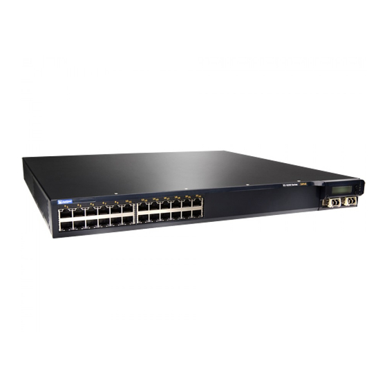
Front Panel of an EX4200 Switch
Description of components on the front panel, including network ports and LEDs.
Rear Panel of an EX4200 Switch
Description of components on the rear panel, including fan tray, ports, and power supplies.
LCD Panel in EX4200 Switches
Details about the LCD panel and navigation buttons for switch status and basic operations.
Uplink Modules in EX4200 Switches
Details about the SFP, SFP+, or XFP uplink modules and their capabilities.
Chassis Status LEDs in EX4200 Switches
Description of the chassis status LEDs on the front panel and their states.
CHAPTER 3 Cooling System and Airflow
Cooling System and Airflow in an EX4200 Switch
Overview of the cooling system, including the fan tray and its function.
Fan Tray
Description of the fan tray and its location at the rear of the chassis.
Airflow Direction in the EX4200 Switch Chassis
Explanation of the airflow path through the switch chassis for cooling.
CHAPTER 4 Power Supplies
Power Supply in EX4200 Switches
Details on the hot-removable power supply unit (FRU) and its redundant nature.
AC Power Supplies
Information on the available AC power supply models and their specifications.
DC Power Supplies
Information on the DC power supply models, dual input feeds, and PoE support.
PoE Power Budget and AC Power Supplies
Explanation of PoE power budget determination based on power supply capacity.
AC Power Supply LEDs in EX4200 Switches
Description of the LEDs on the AC power supply and their states.
CHAPTER 5 Viewing System Information
Dashboard for EX Series Switches
Overview of the J-Web dashboard for viewing system information and its panels.
Graphical Chassis Viewer
Description of the graphical chassis viewer in the dashboard for switch and member status.
System Information Panel
Details on fields like system name, device model, and inventory details.
Health Status Panel
Information on memory utilization, flash, temperature, CPU load, and fan status.
Capacity Utilization Panel
Details on active ports, total ports, MAC table entries, and VLANs.
Alarms Panel
Information displayed about the last five alarms raised in the system.
CHAPTER 6 Preparation Overview
Site Preparation Checklist for EX4200 Switches
Checklist of tasks for preparing a site for EX4200 switch installation.
Environmental Requirements and Specifications for EX Series Switches
Guidelines for installing switches in a dry, clean, well-ventilated, temperature-controlled environment.
Site Electrical Wiring Guidelines
Factors to consider when planning electrical wiring at the site, including RFI and EMC.
Rack Requirements
Guidelines for mounting devices on two-post or four-post racks, including size and strength.
Cabinet Requirements
Specifications for cabinet mounting, including size, clearance, and airflow requirements.
Requirements for Mounting an EX4200 Switch on a Desktop or Wall
Instructions for mounting the switch on a desk, level surface, or wall.
Clearance Requirements for Airflow and Hardware Maintenance for EX4200 Switches
Mandatory clearances around the switch for proper airflow and maintenance access.
CHAPTER 7 Power Specifications and Requirements
Power Specifications for EX4200 Switches
Description of power supply specifications for EX4200 switches.
AC Power Cord Specifications for EX4200 Switches
Details on the type and specifications of the AC power cord supplied.
Calculating the EX Series Switch Fiber-Optic Cable Power Budget
Method for calculating the link's power budget for fiber-optic cable layout.
Calculating the EX Series Switch Fiber-Optic Cable Power Margin
Process for calculating the link's power margin to ensure sufficient signal power.
CHAPTER 8 Transceiver and Cable Specifications
Pluggable Transceivers Supported on EX4200 Switches
List of supported SFP, SFP+, or XFP transceivers and information from Hardware Compatibility Tool.
Pluggable Transceivers Supported on EX Series Switches
Information on hot-removable and hot-insertable transceivers for EX Series switches.
SFP+ Direct Attach Copper Cables for EX Series Switches
Details on SFP+ direct attach copper (DAC) cables, also known as Twinax cables.
Management Cable Specifications
Specifications for cables connecting console (CON) and management (MGMT) ports to management devices.
Understanding EX Series Switches Fiber-Optic Cable Signal Loss, Attenuation, and Dispersion
Explanation of how signal loss, attenuation, and dispersion affect fiber-optic transmission.
CHAPTER 9 Pinout Specifications
Console Port Connector Pinout Information
Pinout information for the RJ-45 console port, used for console management device connection.
USB Port Specifications for an EX Series Switch
Details on tested and supported USB flash drives for EX Series switches.
RJ-45 Management Port Connector Pinout Information
Pinout information for the RJ-45 connector for the management port on Juniper Networks devices.
RJ-45 Port, QSFP+ Port, SFP+ Port, and SFP Port Connector Pinout Information
Description of connector pinout information for various ports like RJ-45, QSFP+, SFP+, and SFP.
RJ-45 to DB-9 Serial Port Adapter Pinout Information
Pinout information for the RJ-45 to DB-9 serial port adapter used for console connection.
Uplink Modules Connector Pinout Information for EX4200 Switches
Pinout information for the uplink module connector on EX4200 switches.
Virtual Chassis Ports Connector Pinout Information for EX4200 Switches
Pinout information for the 68-pin connector cable used for Virtual Chassis ports (VCPs).
CHAPTER 10 Planning the Virtual Chassis
Understanding EX4200, EX4500, and EX4550 Virtual Chassis Hardware Configurations
Information on interconnecting EX4200, EX4500, and EX4550 switches into Virtual Chassis.
Ports Used to Interconnect Virtual Chassis Members
Details on the types of ports used to connect members in a Virtual Chassis configuration.
Number of Switches, Required Software Releases, and Member Roles That You Configure in the Virtual Chassis
Requirements for switch count, software release, and member roles in a Virtual Chassis.
Switch Role and Member ID on the LCD Panel
Information on how the LCD panel displays the switch role and member ID in a Virtual Chassis.
Planning EX4200, EX4500, and EX4550 Virtual Chassis
Considerations for planning Virtual Chassis configurations with EX4200, EX4500, and EX4550 switches.
Virtual Chassis Cabling Configuration Examples for EX4200 Switches
Illustrations and examples of Virtual Chassis cabling configurations for EX4200 switches.
CHAPTER 11 Unpacking the Switch
Unpacking an EX4200 Switch
Step-by-step instructions for unpacking the EX4200 switch from its shipping carton.
Parts Inventory (Packing List) for an EX4200 Switch
List of parts included in the switch shipment and quantities for the EX4200 switch.
Registering Products—Mandatory for Validating SLAs
Instructions for registering hardware products to activate replacement service-level agreements.
CHAPTER 12 Installing the Switch
Installing and Connecting an EX4200 Switch
Overview of the process for installing and connecting an EX4200 switch.
Mounting an EX4200 Switch
Options for mounting the switch in a rack, cabinet, on a desk, or on a wall.
Mounting an EX4200 Switch on a Desk or Other Level Surface
Instructions for mounting the switch on a desk or level surface using rubber feet.
Mounting an EX4200 Switch on Two Posts in a Rack or Cabinet
Procedure for mounting the switch on two posts in a 19-in. rack or cabinet using provided brackets.
Mounting an EX4200 Switch on Four Posts in a Rack or Cabinet
Instructions for mounting the switch on four posts in a rack or cabinet using a rack-mount kit.
Mounting an EX4200 Switch in a Recessed Position in a Rack or Cabinet
Guidance on mounting the switch recessed in a rack or cabinet using specific brackets.
Mounting an EX4200 Switch on a Wall
Instructions for mounting the switch on a wall using a separately orderable wall-mount kit.
Installing and Removing EX4200 Switch Hardware Components
Procedures for installing and removing field-replaceable units (FRUs) from the switch.
CHAPTER 13 Connecting the Switch to Power
Connecting Earth Ground to an EX Series Switch
Procedure for connecting the switch to earth ground for safety and EMI requirements.
Connecting AC Power to an EX4200 Switch
Step-by-step instructions for connecting AC power to the switch.
Connecting DC Power to an EX4200 Switch
Instructions for connecting DC power to the switch, including safety precautions.
CHAPTER 14 Connecting the Switch to the Network
Connecting a Device to a Network for Out-of-Band Management
Method for connecting a device to a management channel via an Ethernet cable and RJ-45 connector.
Connecting a Device to a Management Console by Using an RJ-45 Connector
Procedure for connecting to a console server or management console using the console port.
Connecting a Fiber-Optic Cable
Steps for connecting a fiber-optic cable to an optical transceiver, including laser safety.
CHAPTER 15 Performing Initial Configuration
EX4200 Default Configuration
Description of the factory default configuration file and its settings.
Connecting and Configuring an EX Series Switch (CLI Procedure)
Steps for connecting and configuring an EX Series switch using the Command Line Interface.
Connecting and Configuring an EX Series Switch (J-Web Procedure)
Steps for connecting and configuring an EX Series switch using the J-Web interface.
Configuring the LCD Panel on EX Series Switches (CLI Procedure)
How to configure the LCD panel, including disabling menus or setting custom messages.
CHAPTER 16 Replacing Cooling System Component
Installing a Fan Tray in an EX4200 Switch
Procedure for installing a hot-removable fan tray into the switch chassis.
Removing a Fan Tray from an EX4200 Switch
Procedure for removing a hot-removable fan tray from the switch chassis.
CHAPTER 17 Replacing Power Supply
Installing a Power Supply in an EX4200 Switch
Instructions for installing a hot-removable power supply unit into the switch.
Removing a Power Supply from an EX4200 Switch
Procedure for removing a hot-removable power supply unit from the switch.
CHAPTER 18 Replacing Uplink Module
Installing an Uplink Module in an EX4200 Switch
Steps for installing an optional uplink module into the switch's front panel.
Removing an Uplink Module from an EX4200 Switch
Procedure for removing an optional uplink module from the switch's front panel.
CHAPTER 19 Replacing Transceiver
Installing a Transceiver
Instructions for installing hot-removable transceivers into ports to enable optical connections.
Removing a Transceiver
Procedure for removing hot-removable transceivers from ports, including safety precautions.
CHAPTER 20 Maintaining and Replacing Fiber-Optic Cable
Connecting a Fiber-Optic Cable
Steps for connecting a fiber-optic cable to an optical transceiver, including safety measures.
Disconnecting a Fiber-Optic Cable from a Device
Procedure for safely disconnecting a fiber-optic cable from an optical transceiver.
CHAPTER 21 Replacing a Member Switch to Virtual Chassis
Adding a New EX4200 Switch to an Existing EX4200 Virtual Chassis (CLI Procedure)
Steps to add a new EX4200 switch to an existing EX4200 Virtual Chassis using CLI.
Adding a New Switch from a Different Wiring Closet to an Existing Virtual Chassis
Procedure to add an EX4200 switch from a different wiring closet to a Virtual Chassis.
Adding a New Switch to an Existing Preprovisioned Virtual Chassis Using Autoprovisioning
Method to add switches to a preprovisioned Virtual Chassis using autoprovisioning.
Replacing a Member Switch of a Virtual Chassis Configuration (CLI Procedure)
Procedure to replace a member switch in a Virtual Chassis while retaining configuration.
CHAPTER 22 Maintaining and Replacing Virtual Chassis Cable
Connecting a Virtual Chassis Cable to an EX4200 Switch
Instructions for connecting a Virtual Chassis cable between switches to form a unified switch.
Disconnecting a Virtual Chassis Cable from an EX4200 Switch
Procedure for safely disconnecting a Virtual Chassis cable from the switch.
CHAPTER 23 Contacting Customer Support and Returning the Chassis or Components
Returning an EX4200 Switch or Component for Repair or Replacement
Steps for returning a switch or component for repair or replacement, including RMA process.
Locating the Serial Number on an EX4200 Switch or Component
Methods to find the serial number of the switch or component for support purposes.
Contacting Customer Support to Obtain Return Material Authorization
Process for obtaining an RMA number from JTAC for returning equipment.
Packing an EX4200 Switch or Component for Shipping
Instructions for packing switches or components for shipping, including safety precautions.
CHAPTER 24 Alarms and Syslog Messages
Understanding Alarm Types and Severity Levels on EX Series Switches
Explanation of alarm terms, types, and severity levels for EX Series switches.
Chassis Component Alarm Conditions on EX4200 Switches
Description of chassis component alarm conditions, severity, and remedies for EX4200 switches.
Checking Active Alarms with the J-Web Interface
Steps to view active alarms, including filtering by type, severity, and date range in J-Web.
Monitoring System Log Messages
Procedure to filter and view system log messages for EX Series switches.
CHAPTER 25 Troubleshooting Switch Components
Troubleshooting Network Interfaces on EX4200 Switches
Information on troubleshooting problems with interfaces, especially with SFP/SFP+ transceivers.
Troubleshooting Virtual Chassis Port Connectivity on an EX4200 Switch
Information on troubleshooting issues with Virtual Chassis port (VCP) connections.
Troubleshooting Power Supply Installation Alarms on EX4200 Switches
Information on troubleshooting power supply installation alarms, like 'Unsupported PSU'.
The Switch Displays the “Unsupported PSU” Alarm
Troubleshooting steps when the switch displays an 'Unsupported PSU' alarm due to incompatibility.
CHAPTER 26 General Safety Guidelines and Warnings
General Safety Guidelines and Warnings
Guidelines to ensure personal safety and protect the device from damage during operation.
Definitions of Safety Warning Levels
Explanation of warning symbols like NOTE, CAUTION, and WARNING, and their meanings.
Qualified Personnel Warning
Warning stating that only trained and qualified personnel should install or replace the device.
Warning Statement for Norway and Sweden
Specific warning for equipment connection to an earthed mains socket-outlet in Norway and Sweden.
CHAPTER 27 Fire Safety Requirements
Fire Safety Requirements
Procedures for fire emergency preparedness, safety training, and fire-control equipment.
CHAPTER 28 Installation Safety Guidelines and Warnings
Installation Instructions Warning
Warning to read installation instructions before connecting the device to a power source.
Chassis Lifting Guidelines
Guidelines for safely lifting and moving the device, including weight limits for personnel.
Restricted Access Warning
Warning that the unit is intended for installation in restricted access areas only.
Ramp Warning
Warning against using ramps inclined at more than 10 degrees during installation.
Rack-Mounting and Cabinet-Mounting Warnings
Precautions for safely mounting the device in racks or cabinets to ensure stability.
Wall-Mounting Warning for EX4200 Switches
Warning about the orientation of the chassis when mounted vertically on a wall.
Grounded Equipment Warning
Reminder to ensure the device is properly grounded during normal use.
CHAPTER 29 Radiation and Laser Safety Guidelines and Warnings
Laser and LED Safety Guidelines and Warnings
Guidelines for safe handling of laser transmitters and optical transceivers.
General Laser Safety Guidelines
Safety guidelines to prevent eye injury when working around ports with optical transceivers.
Class 1 Laser Product Warning
Warning indicating the product is a Class 1 laser product.
Class 1 LED Product Warning
Warning indicating the product is a Class 1 LED product.
Laser Beam Warning
Warning not to stare into the laser beam or view it directly with optical instruments.
Radiation from Open Port Apertures Warning
Warning about potential invisible radiation from open port apertures without fiber cable.
CHAPTER 30 Maintenance and Operational Safety Warnings
Maintenance and Operational Safety Guidelines and Warnings
Guidelines and warnings to observe during maintenance activities for devices.
Battery Handling Warning
Warning regarding incorrect battery replacement and disposal of used batteries.
Jewelry Removal Warning
Warning to remove jewelry before working on equipment connected to power lines.
Lightning Activity Warning
Warning not to work on the system or connect/disconnect cables during lightning activity.
Operating Temperature Warning
Guidance to prevent overheating by not operating outside recommended ambient temperature.
Product Disposal Warning
Instructions for handling device disposal according to national laws and regulations.
CHAPTER 31 Electrical Safety Guidelines and Warnings
General Electrical Safety Guidelines and Warnings
General safety guidelines and warnings related to electrical hazards and device operation.
Action to Take After an Electrical Accident
Steps to follow in case of an electrical accident, including disconnecting power and seeking aid.
Prevention of Electrostatic Discharge Damage
Guidelines to minimize potential for ESD damage to sensitive components.
AC Power Electrical Safety Guidelines
Electrical safety guidelines specific to devices with AC power supplies.
AC Power Disconnection Warning
Warning to unplug all power cords before working on the device or near power supplies.
DC Power Electrical Safety Guidelines for Switches
Electrical safety guidelines specific to DC-powered switches and their connections.
DC Power Grounding Requirements and Warning
Requirements for DC power grounding connections and warnings about proper grounding.
DC Power Wiring Sequence Warning
Warning about the correct sequence for connecting and disconnecting DC power supply wires.
DC Power Wiring Terminations Warning
Guidelines on using approved wiring terminations for stranded DC wiring.
Multiple Power Supplies Disconnection Warning
Ensuring all power connections are disconnected for devices with multiple power supplies.
CHAPTER 32 Agency Approvals and Compliance Statements
Agency Approvals for EX Series Switches
List of standards that EX Series hardware devices comply with for safety and EMC.
Compliance Statements for EMC Requirements for EX Series Switches
Description of EMC requirements for hardware devices, broken down by country/region.
Compliance Statements for Acoustic Noise for EX Series Switches
Information on acoustic noise levels of EX Series switches, below 70 dB(A) per EN ISO 7779.
Need help?
Do you have a question about the EX4200-48PX and is the answer not in the manual?
Questions and answers