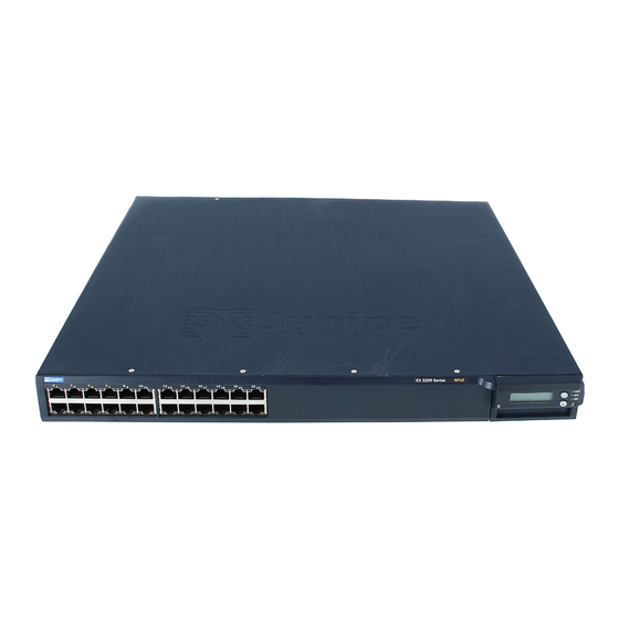
Juniper EX 3200 Manual
Connecting dc power to switch
Hide thumbs
Also See for EX 3200:
- Quick start (2 pages) ,
- Complete hardware manual (194 pages) ,
- Connecting (4 pages)
Table of Contents
Advertisement
Quick Links
Connecting DC Power to an EX 3200 or EX 4200 Switch
LEDs
The power supply in an EX 3200 or EX 4200 switch is a hot-removable and
hot-insertable field-replaceable unit (FRU) located on the rear panel.
Figure 1: DC Power Supply in EX 3200 and EX 4200 Switches
Locking lever
Handle
Fan exhaust
WARNING: DC-powered EX 3200 and EX 4200 switches are intended for installation
only in a restricted access location.
Ensure that you have the following parts and tools available to connect DC power to
an EX 3200 or EX 4200 switch:
Electrostatic discharge (ESD) grounding strap
DC power source cables (12 14 AWG) with ring lug (Molex 190700067 or
equivalent) (not provided)
Phillips (+) screwdriver, number 2
Before you begin connecting DC power to an EX 3200 or EX 4200 switch:
Ensure that you have taken the necessary precautions to prevent ESD damage
(see Prevention of Electrostatic Discharge Damage on EX-series Switches).
Ensure that you have connected the switch chassis to earth ground.
CAUTION: Before you connect power to the switch, a licensed electrician must attach
a cable lug to the grounding and power cables that you supply. A cable with an
incorrectly attached lug can damage the switch (for example, by causing a short
circuit).
To meet safety and electromagnetic interference (EMI) requirements and to ensure
proper operation, you must connect EX 3200 and EX 4200 switches to earth ground
before you connect them to power. For installations that require a separate grounding
conductor to the chassis, use the protective earthing terminal on the switch chassis
Terminal block
Connecting DC Power to an EX 3200 or EX 4200 Switch
1
Advertisement
Table of Contents

Summary of Contents for Juniper EX 3200
- Page 1 Connecting DC Power to an EX 3200 or EX 4200 Switch The power supply in an EX 3200 or EX 4200 switch is a hot-removable and hot-insertable field-replaceable unit (FRU) located on the rear panel. Figure 1: DC Power Supply in EX 3200 and EX 4200 Switches...
- Page 2 Connecting Earth Ground to an EX-series Switch. Install the power supply in the chassis. For instructions on installing a power supply in an EX 3200 or EX 4200 switch, see Installing a Power Supply in an EX 3200 or EX 4200 Switch.
- Page 3 Figure 2: Removing the Terminal Block Cover in a DC Power Supply in EX 3200 and EX 4200 Switches Remove the screws on the terminals using the Phillips (+) screwdriver, number 2. Save the screws. WARNING: Ensure that the power cables do not block access to switch components or drape where people can trip on them.
- Page 4 8 lb-in. (0.9 Nm) and 9 lb-in. (1.02 Nm) of torque to the screws. Figure 3: Securing Ring Lugs to the Terminals on the DC Power Supply in EX 3200 and EX 4200 Switches Replace the terminal block cover and secure it using the screw. Use the Phillips (+) screwdriver, number 2 to tighten the screw.


Need help?
Do you have a question about the EX 3200 and is the answer not in the manual?
Questions and answers