Table of Contents
Advertisement
QQ
3 7 63 1515 0
CD RECEIVER
DEH-4090MP
DEH-6010MP
This service manual should be used together with the following manual(s):
Model No.
TE
L 13942296513
CX-3195
www
For details, refer to "Important Check Points for Good Servicing".
.
PIONEER CORPORATION
PIONEER ELECTRONICS (USA) INC. P.O. Box 1760, Long Beach, CA 90801-1760, U.S.A.
PIONEER EUROPE NV Haven 1087, Keetberglaan 1, 9120 Melsele, Belgium
PIONEER ELECTRONICS ASIACENTRE PTE. LTD. 253 Alexandra Road, #04-01, Singapore 159936
PIONEER CORPORATION 2007
http://www.xiaoyu163.com
Order No.
Mech.Module
CRT3815
S10.5COMP2
x
ao
y
i
4-1, Meguro 1-chome, Meguro-ku, Tokyo 153-8654, Japan
http://www.xiaoyu163.com
8
DEH-4090MP/XN/ID
/XN/UR
Q Q
3
6 7
1 3
CD Mech. Module : Circuit Descriptions, Mech. Descriptions, Disassembly
u163
.
2 9
9 4
2 8
Remarks
1 5
0 5
8
2 9
9 4
m
co
K-ZZW. OCT. 2007 Printed in Japan
9 9
ORDER NO.
CRT4033
/XN/ID
2 8
9 9
Advertisement
Table of Contents

Related Manuals for Pioneer DEH-6010MP


Summarization of Contents
SAFETY INFORMATION
CAUTION
General warnings and precautions for service technicians.
Safety Precautions for Laser Diode
Specific safety advice regarding laser diode operation and handling.
[Important Check Points for Good Servicing]
Product Safety Checks
Conforming to regulations, safe servicing environment, and using genuine parts.
Post-Repair Procedures
Covers adjustments, lubrication, cleaning, and shipping preparation.
SERVICE PRECAUTIONS
General Service Precautions
Conforming to regulations and following safety instructions during servicing.
Soldering Guidelines
Using lead-free solder and appropriate irons for environmental protection.
SPECIFICATIONS
Technical Specifications
Detailed specs for DEH-4090MP/XN/ID: general, audio, CD, FM/AM tuner.
Disc and Content Format
Supported disc and content formats, including CD, CD TEXT, and Windows Media.
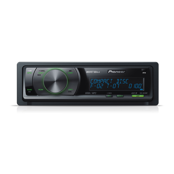
Panel and Button Functions
Overview and function of head unit and remote control buttons.
Connection Diagram
Wiring diagram for power, speakers, and accessories.
BASIC SERVICE PROCEDURES
Post-Service Checkpoints
Confirmation steps after repairs, including complaint resolution and appearance.
PCB Component Locations
Identification and location of main PCB units: Panel, Tuner Amp, Keyboard, CD Core.
Service Jigs and Materials
List of jigs, greases, and cleaning tools for servicing.
DIAGNOSIS AND TROUBLESHOOTING
Operational Flowchart
Step-by-step flowchart for power-on operation and initial system checks.
Error Code Reference
Table of error messages, codes, classes, and potential causes.
Connector Functionality
Description of functions for various rear panel connectors.
SERVICE MODES
CD Test Mode Operation
Procedure to enter and operate the CD Test Mode for functional testing.
CD Test Mode Flowchart
Flowchart detailing key operations and test modes within the CD mechanism.
DISASSEMBLY PROCEDURES
Front Panel Assembly Removal
Steps to remove keyboard unit, grille, knob, holder, case, and panel.
Main Unit Disassembly
Procedures for removing CD mechanism, panel assembly, and tuner amp units.
Core Component Removal
Steps for removing CD core unit and pickup unit.
SETTINGS AND ADJUSTMENTS
CD Mechanism Adjustment
Cautions and test mode procedures for CD mechanism module adjustment.
Grating Check Procedure
Method to check grating angle after PU unit replacement, including waveforms.
PCL Output Verification
Confirmation of PCL output by shifting a terminal and checking clock signal frequency.
PARTS IDENTIFICATION
Packing Components List
Exploded view and parts list for the product's packing contents.
Exterior Parts - Part 1
Exploded view and parts list for exterior components.
Exterior Parts - Part 2
Exploded view and parts list for additional exterior components.
CD Mechanism Module Parts
Exploded view and parts list for the CD mechanism module.
SCHEMATIC DIAGRAMS
Overall System Connection Diagram
High-level overview of connections between main units: Tuner, CD, Panel.
Keyboard Unit Schematic
Schematic diagram for the keyboard unit showing button connections and controls.
CD Mechanism Module Schematic
Detailed schematic of the CD mechanism module's internal connections.
Signal Waveform Examples
Oscilloscope waveform examples for various test points in the CD core unit.
PCB LAYOUT DIAGRAMS
Tuner Amplifier Unit PCB Layout
PCB connection diagram for the Tuner Amp Unit, showing component placement.
Keyboard Unit PCB Layout
PCB connection diagram for the Keyboard Unit, illustrating component layout.
CD Core Unit PCB Layout
PCB connection diagram for the CD Core Unit, showing component placement.
Panel Unit PCB Layouts
PCB connection diagrams for the Panel Unit (Side A and Side B).
ELECTRICAL PARTS REFERENCE
Important Parts Notes
Notes on part numbers, chip components, and safety factors.
Resistor Component List
Comprehensive list of resistors with circuit symbols, part numbers, and locations.
Capacitor Component List
Comprehensive list of capacitors with circuit symbols, part numbers, and locations.
Miscellaneous Components List
List of miscellaneous parts: ICs, transistors, LEDs, inductors.
Need help?
Do you have a question about the DEH-6010MP and is the answer not in the manual?
Questions and answers