Advertisement
QQ
3 7 63 1515 0
S
ervice
M anua l
BRIDGEABLE FOUR-CHANNEL POWER AMPLIFIER
GM-X424
GM-X324
CONTENTS
1. SAFETY INFORMATION ............................................1
2. EXPLODED VIEWS AND PARTS LIST .......................2
3. SCHEMATIC DIAGRAM .............................................6
TE
L 13942296513
4. PCB CONNECTION DIAGRAM ..................................8
1. SAFETY INFORMATION
This service manual is intended for qualified service technicians; it is not meant for the casual do-it-yourselfer.
Qualified technicians have the necessary test equipment and tools, and have been trained to properly and safely repair
complex products such as those covered by this manual.
Improperly performed repairs can adversely affect the safety and reliability of the product and may void the warranty.
If you are not qualified to perform the repair of this product properly and safely, you should mot risk trying to do so
and refer the repair to a qualified service technician.
UC model
CAUTION
This service manual is intended for qualified service technicians; it is not meant for the casual do-it-yourselfer.
Qualified technicians have the necessary test equipment and tools, and have been trained to properly and safely repair
complex products such as those covered by this manual.
Improperly performed repairs can adversely affect the safety and reliability of the product and may void the warranty.
If you are not qualified to perform the repair of this product properly and safely; you should not risk trying to do so
and refer the repair to a qualified service technician.
WARNING
Lead in solder used in this product is listed by the California Health and Welfare agency as a known reproductive toxi-
www
cant which may cause birth defects or other reproductive harm (California Health & Safety Code, Section 25249.5).
When servicing or handling circuit boards and other components which contain lead in solder, avoid unprotected skin
contact with the solder. Also, when soldering do not inhale any smoke or fumes produced.
.
PIONEER ELECTRONIC CORPORATION
PIONEER ELECTRONICS SERVICE INC.
PIONEER ELECTRONIC [EUROPE] N.V.
PIONEER ELECTRONICS ASIACENTRE, PTE.LTD. 501 Orchard Road, #10-00, Wheelock Place, Singapore 238880
C PIONEER ELECTRONIC CORPORATION 1998
http://www.xiaoyu163.com
x
ao
u163
y
i
P.O.Box 1760, Long Beach, CA 90801-1760 U.S.A.
Haven 1087 Keetberglaan 1, 9120 Melsele, Belgium
http://www.xiaoyu163.com
2 9
8
X1R/UC
5. ELECTRICAL PARTS LIST ........................................12
6. ADJUSTMENT..........................................................16
7. GENERAL INFORMATION .......................................16
3
6 7
1 3
1 5
7.1 DISASSEMBLY ...................................................16
8. OPERATIONS AND SPECIFICATIONS.....................17
co
.
4-1, Meguro 1-Chome, Meguro-ku, Tokyo 153-8654, Japan
9 4
2 8
ORDER NO.
CRT2168
X1R/UC, ES, EW
0 5
8
2 9
9 4
2 8
m
K-ZEU. JAN. 1998 Printed in Japan
9 9
9 9
Advertisement
Table of Contents

Related Manuals for Pioneer GM-X324 X1R/UC


Summarization of Contents
1. Safety Information
Caution for Technicians
Important safety advice for qualified technicians regarding product repair.
Warning: Lead in Solder
Warning about lead in solder and safe handling to avoid health risks.
2. Exploded Views and Parts Lists
2.1 Packing Contents
Lists all parts included in the product packaging.
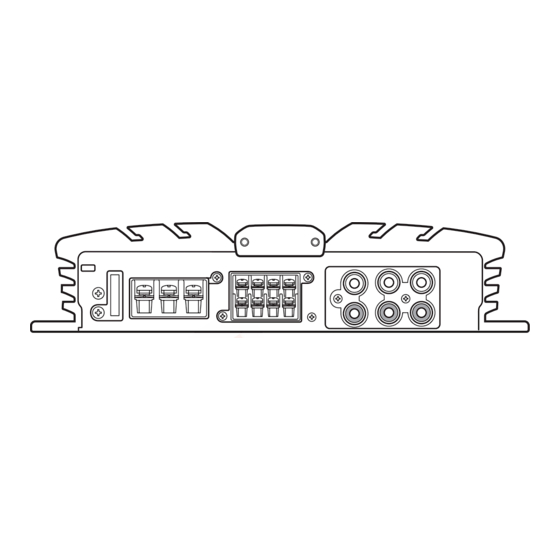
2.2 Exterior View Diagram
Exploded view of the unit's exterior components for identification.
Exterior Section Parts List
Detailed list of external components and their corresponding part numbers.
4. PCB Connection Diagrams
Mother PCB Connection Diagram
Diagram showing component layout and connections on the Mother PCB.
Isolator PCB Connection Diagram
Diagram showing component layout and connections on the Isolator PCB.
5. Electrical Parts List
Integrated Circuits & Miscellaneous
Lists integrated circuits and other miscellaneous electronic components.
Semiconductor Devices
Lists transistors, FETs, diodes, and LEDs with circuit symbols and part numbers.
Inductors, Transformers & Thermistors
Lists inductors, transformers, and thermistors with part numbers.
Controls and Fuses
Lists switches, volume controls, and fuses used in the unit.
Resistors
Detailed list of resistors used in the circuit with part numbers.
Capacitors
Comprehensive list of capacitors with specifications and part numbers.
7. General Information
7.1 Disassembly Procedure
Steps for disassembling the unit, including case and amp unit removal.
8. Operations and Specifications
Unit Settings and Controls
Guidance on setting operational controls like gain, RCA input, and filters.
Need help?
Do you have a question about the GM-X324 X1R/UC and is the answer not in the manual?
Questions and answers