Table of Contents
Advertisement
Quick Links
Service
Manual
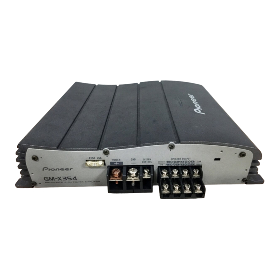
BRIDGEABLE FOUR-CHANNEL POWER AMPLIFIER
GM-X354
CONTENTS
1. SAFETY INFORMATION............................................2
2. EXPLODED VIEWS AND PARTS LIST ......................2
3. SCHEMATIC DIAGRAM.............................................6
4. PCB CONNECTION DIAGRAM..................................8
5. ELECTRICAL PARTS LIST........................................12
PIONEER CORPORATION
PIONEER ELECTRONICS SERVICE INC.
PIONEER EUROPE N.V.
Haven 1087 Keetberglaan 1, 9120 Melsele, Belgium
PIONEER ELECTRONICS ASIACENTRE PTE.LTD. 253 Alexandra Road, #04-01, Singapore 159936
C PIONEER CORPORATION 2000
GM-X354/X1R/EW
4-1, Meguro 1-Chome, Meguro-ku, Tokyo 153-8654, Japan
P.O.Box 1760, Long Beach, CA 90801-1760 U.S.A.
X1R/UC,EW,ES
6. ADJUSTMENT .........................................................15
7. GENERAL INFORMATION.......................................16
7.1 DISASSEMBLY ..................................................16
8. OPERATIONS AND SPECIFICATIONS ....................17
K-ZZS. NOV. 2000 Printed in Japan
ORDER NO.
CRT2615
Advertisement
Table of Contents

Related Manuals for Pioneer GM-X354


Summary of Contents for Pioneer GM-X354
-
Page 1: Table Of Contents
PIONEER ELECTRONICS SERVICE INC. P.O.Box 1760, Long Beach, CA 90801-1760 U.S.A. PIONEER EUROPE N.V. Haven 1087 Keetberglaan 1, 9120 Melsele, Belgium PIONEER ELECTRONICS ASIACENTRE PTE.LTD. 253 Alexandra Road, #04-01, Singapore 159936 C PIONEER CORPORATION 2000 K-ZZS. NOV. 2000 Printed in Japan... -
Page 2: Safety Information
GM-X354 1. SAFETY INFORMATION - GM-X354/X1R/UC CAUTION This service manual is intended for qualified service technicians; it is not meant for the casual do-it-yourselfer. Qualified technicians have the necessary test equipment and tools, and have been trained to properly and safely repair complex products such as those covered by this manual. - Page 3 GM-X354 NOTE: - Parts marked by “*” are generally unavailable because they are not in our Master Spare Parts List. ∇ mark on the product are used for disassembly. - Screws adjacent to - PACKING SECTION PARTS LIST Part No.
- Page 4 GM-X354 2.2 EXTERIOR...
- Page 5 See Contrast table(2) 18 Terminal(CN903) CKF1059 19 Fuse(25A) HEK0025 20 Pin Jack(CN802) HKB0001 (2) CONTRAST TABLE GM-X354/X1R/UC, EW and ES are constructed the same except for the following: Part No. Mark No. Description GM-X354/X1R/UC GM-X354/X1R/EW GM-X354/X1R/ES 10 Panel HNB0125 HNB0143...
-
Page 6: Schematic Diagram
GM-X354 3. SCHEMATIC DIAGRAM 3.1 AMP UNIT Note: When ordering service parts, be sure to refer to “EXPLODED VIEWS AND PARTS LIST” or “ELECTRICAL PARTS LIST”. AMP UNIT 80Hz 12dB/OCTAVE LPF/HPF SELECT S101-1 GAIN=1 L+ R+ L- R- INPUT SPEAKER... - Page 7 GM-X354 SELECT GAIN = 5.2 - 27.5 dB LPF/HPF SELECT S301-1 GAIN...
-
Page 8: Pcb Connection Diagram
GM-X354 4. PCB CONNECTION DIAGRAM 4.1 AMP UNIT AMP UNIT NOTE FOR PCB DIAGRAMS 1. The parts mounted on this PCB GAIN include all necessary parts for several destination. For further information for respective destinations, be sure to check with the schematic LPF/ diagram. - Page 9 GM-X354 SIDE A FUSE...
- Page 10 GM-X354 AMP UNIT POWER...
- Page 11 GM-X354 SIDE B...
-
Page 12: Electrical Parts List
CKS.., CCS.., CSZS..=====Circuit Symbol and No.===Part Name Part No. =====Circuit Symbol and No.===Part Name Part No. ------ ------------------------------------------ ------------------------- ------ ------------------------------------------ ------------------------- Unit Number : HWH0151(GM-X354/X1R/UC) Transistor 2SD1919 Transistor 2SB1277 : HWH0150(GM-X354/X1R/EW) Transistor 2SB1277 : HWH0152(GM-X354/X1R/ES) Transistor 2SD1919 Unit Name... - Page 13 GM-X354 =====Circuit Symbol and No.===Part Name Part No. =====Circuit Symbol and No.===Part Name Part No. ------ ------------------------------------------ ------------------------- ------ ------------------------------------------ ------------------------- RD1/4PU561J 0.22Ω CCN1013 RD1/4PU561J 0.22Ω CCN1013 RD1/4PU161J RS1/2PMF100J RD1/4PU161J RS1/10S912J RD1/4PU473J RS1/10S103J RD1/4PU473J RS1/10S123J RD1/4PU221J RS1/10S223J RD1/4PU562J RS1/10S222J RD1/4PU222J...
- Page 14 GM-X354 =====Circuit Symbol and No.===Part Name Part No. =====Circuit Symbol and No.===Part Name Part No. ------ ------------------------------------------ ------------------------- ------ ------------------------------------------ ------------------------- RS1/10S223J RD1/4PU222J RS1/10S472J RD1/4PU103J RD1/4PU101J RD1/4PU104J RD1/4PU221J RD1/4PU153J RD1/4PU152J CAPACITORS RD1/4PU331J RD1/4PU331J CFTLA274J50 RS1/10S471J CFTLA154J50 RS1/10S471J CFTLA124J50 RS1/10S333J CFTLA124J50...
-
Page 15: Adjustment
GM-X354 =====Circuit Symbol and No.===Part Name Part No. =====Circuit Symbol and No.===Part Name Part No. ------ ------------------------------------------ ------------------------- ------ ------------------------------------------ ------------------------- CCSQCH330J50 CFTLA103J50 CCSQCH330J50 CFTLA103J50 CCSQCH220J50 CFTLA334J50 CFTLA223J50 CFTLA103J50 CFTLA333J50 CEAS100M16 CCSQCH101J50 CEAS221M10 CCSQCH101J50 CQMA102J50 CQMA102J50 CEAS2R2M50 220µF/10V CCH1036 CEAS101M16 CFTLA103J50 3300µF/16V... -
Page 16: General Information
GM-X354 7. GENERAL INFORMATION 7.1 DISASSEMBLY Removing the Case and the Panel (Fig.1) Case Remove the four screws. Remove the two screws. Remove the three screws and then remove the Case. Remove the six screws and then remove the Panel. -
Page 17: Operations And Specifications
GM-X354 8. OPERATIONS AND SPECIFICATIONS 8.1 OPERATIONS - GM-X354/X1R/EW... - Page 18 GM-X354...
- Page 19 GM-X354 Connection Diagram Fuse (30 A) Special red battery wire [RD-223] (sold separately) Grommet After making all other connections at the amplifier, connect the battery wire terminal of the amplifier to the positive (+) terminal of the battery. Fuse (30 A) Ground wire (Black) [RD-223] (sold separately) Connect to metal body or chassis.
- Page 20 GM-X354 8.2 SPECIFICATIONS - GM-X354/X1R/UC Power source....................14.4 V DC (10.8 — 15.1 V allowable) Grounding system ........................Negative type Current consumption ..................18.1 A (at continuous power, 4 Ω) Idle current ........................5 — 25 mA Average current drawn* ..................6.6 A (4 Ω for four channels) ..........................
- Page 21 GM-X354 - GM-X354/X1R/ES Power source ....................14.4 V DC (10.8 — 15.1 V allowable) Grounding system .......................... Negative type Current consumption ..................18.1 A (at continuous power, 4 Ω) Idle current ........................5 — 25 mA Average current drawn* ..................6.6 A (4 Ω for four channels) ..........................9.0 A (4 Ω...
Need help?
Do you have a question about the GM-X354 and is the answer not in the manual?
Questions and answers