Advertisement
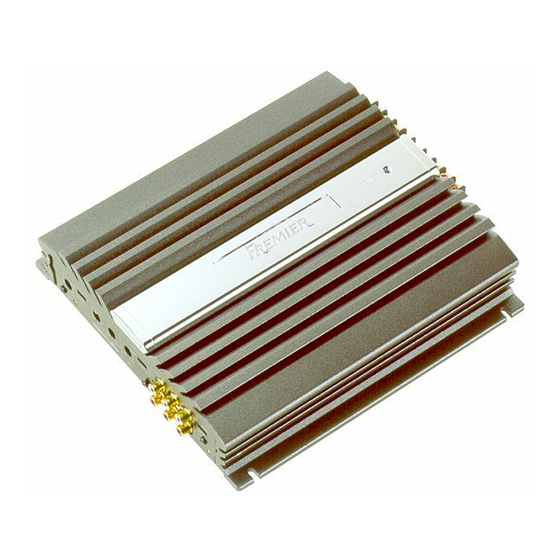
BRIDGEABLE FOUR-CHANNEL POWER AMPLIFIER
GM-X434
GM-X334
CONTENTS
1. SAFETY INFORMATION ............................................2
2. EXPLODED VIEWS AND PARTS LIST .......................2
3. SCHEMATIC DIAGRAM .............................................6
4. PCB CONNECTION DIAGRAM ................................12
5. ELECTRICAL PARTS LIST ........................................16
PIONEER ELECTRONIC CORPORATION
PIONEER ELECTRONICS SERVICE INC.
PIONEER ELECTRONIC [EUROPE] N.V.
PIONEER ELECTRONICS ASIACENTRE PTE.LTD. 253 Alexandra Road, #04-01, Singapore 159936
C PIONEER ELECTRONIC CORPORATION 1999
GM-X434/X1R/UC
X1R/UC,EW,ES
4-1, Meguro 1-Chome, Meguro-ku, Tokyo 153-8654, Japan
P.O.Box 1760, Long Beach, CA 90801-1760 U.S.A.
Haven 1087 Keetberglaan 1, 9120 Melsele, Belgium
6. ADJUSTMENT..........................................................20
7. GENERAL INFORMATION .......................................20
7.1 IC .........................................................................20
7.2 DISASSEMBLY ...................................................22
8. OPERATIONS AND SPECIFICATIONS.....................23
K-ZZA. JAN. 1999 Printed in Japan
ORDER NO.
CRT2358
X1R/UC
Advertisement
Table of Contents

Related Manuals for Pioneer GM-X334


Summarization of Contents
Safety Information
Safety Precautions and Warnings
Crucial safety guidelines and warnings for safe operation and maintenance of the amplifier unit.
Exploded Views and Parts List
Packing Section Parts List
Lists all parts included in the product's packaging and accessories.
Model Contrast Table
Details part number differences and availability across various product models.
Owner's Manual Variants
Information on specific owner's manuals available for each model variant.
Schematic Diagram
Overall Circuit Connection Diagram
High-level diagram showing the main circuit connections and signal flow.
PCB Connection Diagram
Amp Unit PCB Layout
Illustrates component placement and routing on the main amplifier circuit board.
Electrical Parts List
Component Identification
Lists integrated circuits, transistors, diodes, and inductors with their part numbers.
Resistor Specifications
Details all resistors used, including their circuit symbols, part numbers, and values.
Capacitor Specifications
Details all capacitors used, including their circuit symbols, part numbers, and values.
General Information
Integrated Circuit Details
Provides specific information on key integrated circuits used in the unit.
PA2027A IC Block Diagram
Visual representation of the PA2027A IC's internal functions and pin assignments.
Operations and Specifications
Unit Operation Guide
Instructions for setting controls like Gain, LPF/HPF, and Bass Boost.
Technical Performance Data
Comprehensive specifications covering power, frequency response, and dimensions.
Need help?
Do you have a question about the GM-X334 and is the answer not in the manual?
Questions and answers