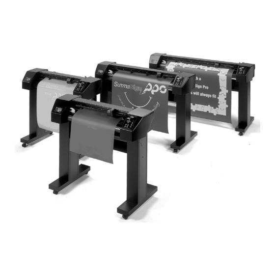
Table of Contents
Advertisement
Quick Links
Advertisement
Table of Contents

Summarization of Contents
Introduction to SummaSign Service Manual
1. Overview of SummaSign Cutters
Introduces the SummaSign Service Manual, its purpose, and scope.
2. Manual Organization and Structure
Details the structure and contents of the service manual's various sections.
Section 1 Keyboard Controls
The Control Panel Functions
Explains the functions of the liquid crystal display and control panel keys for operation.
Normal Operation Modes
Covers on line, off line, and local operation modes for cutter control.
The User Configuration Menu
Guides users on configuring cutter operating parameters and saving custom settings.
Section 2 Replacement Guidelines
Removing the Left-Hand Cover
Step-by-step instructions for safely removing the left-hand cover.
Replacing the X-Motor in Older Models
Detailed procedure for replacing the X-motor in specific older SummaSign models.
Replacing the Main PCB
Comprehensive guide for replacing the main printed circuit board (PCB).
Replacing the Drag or Tangential Head
Instructions for replacing the cutting head assembly, including differences for drag/tangential types.
Replacing the Y-Belt
Provides the procedure for replacing the Y-axis drive belt.
Replacing the Sensors
Details the process for replacing the front and rear media sensors.
Section 3 Maintenance Procedures
Cleaning the Drive System
Instructions on cleaning the drive drum sleeves to maintain media traction.
Operating Voltage Conversion
Explains how to change the AC voltage setting and fuses for different power inputs.
Section 4 Calibration Procedures
Machine Type Configuration
Procedure for setting the correct machine type after PCB replacement or system reset.
Media Calibration Process
Instructions for recalibrating the machine for accurate media handling and cutting.
Head Calibration Methods
Covers knife and coil calibration procedures for optimal cutting performance.
OPOS Calibration (Optional)
Explains the calibration process for the OPOS optical positioning system.
Section 5 Error Codes and Troubleshooting
Motor Hot Error
Addresses the 'MOTOR HOT' message, its cause, and recommended actions.
X-Axis Movement Errors
Details fatal errors related to X-axis movement, including media crash causes and fixes.
High Line Voltage Error
Explains errors from excessive input voltage and necessary troubleshooting steps.
NVRAM Failures and Messages
Covers critical NVRAM errors and potential data loss issues.
6. Figures and Diagrams
Left Side Component Views
Detailed drawings of components located on the left side of the machine.
Keyboard Assembly Diagram
Detailed drawings of the keyboard assembly and its parts.
Section 7 Spare Parts List
SummaCut D500 Spare Parts
List of spare parts for the SummaCut D500 model.
SummaSign D610 Spare Parts
List of spare parts for the SummaSign D610 model.
SummaSign T610 Spare Parts
List of spare parts for the SummaSign T610 model.
SummaSign D750 Spare Parts
List of spare parts for the SummaSign D750 model.
SummaSign T750 Spare Parts
List of spare parts for the SummaSign T750 model.
SummaSign D1010 Spare Parts
List of spare parts for the SummaSign D1010 model.
SummaSign T1010 Spare Parts
List of spare parts for the SummaSign T1010 model.
SummaSign D1300 Spare Parts
List of spare parts for the SummaSign D1300 model.
SummaSign T1300 Spare Parts
List of spare parts for the SummaSign T1300 model.
Appendix A: Left Side Removal Procedure
Procedure for Left Side Removal
Step-by-step instructions for safely removing the left side panel of the machine.
Appendix C: Pinch Roll Lever Play Adjustment
Procedure to Set Pinch Roll Lever Play
Steps to check and adjust the pinch roll lever play for correct tracking.
Appendix D: Motor Replacement on T-Head
Procedure to Change Motor on T-Head
Detailed procedure for replacing the motor on a T-head assembly.


Need help?
Do you have a question about the SummaSign T1300 PRO and is the answer not in the manual?
Questions and answers