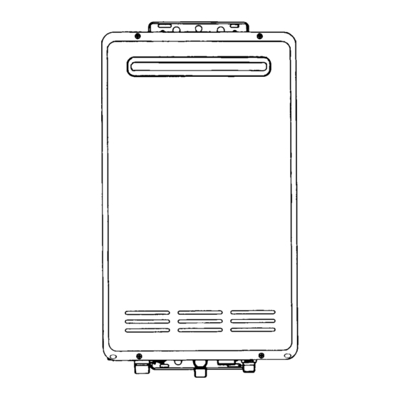
Summarization of Contents
Key Features and Benefits
Installation and Design Features
Details on the appliance's compact design, low noise, and installation ease.
Safety and Economy Aspects
Highlights safety devices, micro-computer control, and energy-efficient operation.
Water Flow and Temperature Controls
Explains water supply capacity, temperature control range, and over-temperature protection.
Temperature Locking Functionality
Describes the feature to lock water temperature between 37°C and 43°C while flowing.
Remote Control Operation and Models
Kitchen and Bathroom Remote Controls
Details on MC-33-3A and BC-45-3A remote controls, their features, and displays.
Third Remote Control Option
Information on the availability of the BSC-45-3A for second bathrooms or ensuites.
Critical Safety Devices and Functions
Flame Failure and Overheat Protection
Describes flame rod monitoring and the overheat protection device for safety.
Water Flow and Thermal Safety Mechanisms
Explains 'No Water' detection, thermal fuse, and pressure relief valve functions.
Frost Protection and Temperature Cut-Off
Details automatic frost protection and the 3°C over-temperature cut-off feature.
Internal Component Layout (Cut-away)
Cut-away Diagram for REU-2008, 2408, 2424
Illustrates the internal structure and placement of key components for specific models.
Cut-away Diagram for REU-2007
Illustrates the internal structure and placement of key components for the REU-2007 model.
Dip Switch Configuration and Settings
DIP Switches Explained
Explanation of the function and layout of the DIP switches on the PCB.
Top and Bottom Switch Settings
Details on top switch settings (1-8) and bottom switch settings (1-3) for appliance configuration.
Settings for Gas Type and Flow
Instructions for setting dip switches related to gas type and maximum water flow selection.
Settings for Temperature Limits
Configuration of dip switches to set fixed or upper limit hot water temperatures.
Settings for Modified PCBs
Tables and diagrams for dip switch settings on modified PCBs.
Setting 85°C Output with Modified PCBs
Procedure for achieving 85°C output on Heavy Duty 20 models using modified PCBs.
Key Internal Components Overview
Mechanical Water Regulator and Preset Bypass
Explanation of the water regulator's role in maintaining stable temperature and flow.
Burner, Solenoid Valve, and Fan Components
Details on the burner assembly, changeover solenoid valve, and combustion fan operation.
Water Flow Sensor and Control (2008/2408/2424)
Explanation of water flow sensing and control mechanisms for specific models.
Water Flow Sensor and Control (REU-2007)
Description of the mechanical water flow control device and sensor for the REU-2007.
Operational Sequence Time Charts
Normal Combustion Sequence Timing
Diagram illustrating the timing of components during normal combustion operation.
Error Sequence Timing (Ignition/Flame Failure)
Diagram showing timing for ignition and flame failure error sequences.
Pre-purge Defect Sequence Timing
Diagram showing timing for pre-purge defect sequences.
REU-2007 Specific Sequence Timing
Sequence timing diagrams specific to the REU-2007 model for errors and purge defects.
Overall Operation Flowchart
Operation Flowchart Completion
Continues the operational flowchart, detailing logic paths and states.
Principles of Appliance Operation
Detailed Operation Logic and Control
Explains how the PCB controls heating, fan speed, and gas flow based on sensor inputs.
General Fault Diagnosis Procedures
Checking Power Supply and Fuse
Procedure to check for blown fuses and proper power supply to the appliance.
Main Transformer and PCB Checks
Steps to test the main transformer and related PCB connections for faults.
Remote Control and Water Flow Sensor Diagnosis
Troubleshooting steps for remote controls and the water flow sensor.
Flame Rod and Thermistor Fault Checks
Procedures to diagnose issues with the flame rod and water temperature thermistor.
Combustion Fan and Sparker Diagnosis
Steps to check the combustion fan and sparker for proper operation.
Solenoid Valve (SV1, SV2) Diagnostics
Checks for main gas solenoid valve (SV1) and change over solenoid valve (SV2) functionality.
Safety Device and Earth Lead Checks
Diagnosing thermal fuse, overheat switch, flame rod, and earth lead issues.
Solenoid Valve (SV3) and Thermal Fuse Checks
Diagnosing SV3 solenoid valve and thermal fuse for errors and non-operation.
Flame Failure and Water Temperature Adjustment Issues
Troubleshooting flame failure causes and problems with adjusting water temperature.
Modulating Valve and Water Flow Servo Diagnostics
Steps to diagnose the modulating valve and water flow servo for operational faults.
Anti-Frost Heater and Frost Sensing Switch Checks
Diagnosing issues with the anti-frost heater and frost sensing switch.
Electrical Component Analysis Guide
Electrical Component Analysis (Continued)
Further steps for analyzing electrical components and their potential faults.
Electrical Component Analysis (Troubleshooting)
Detailed analysis of electrical components, including voltage and resistance checks.
Electrical Component Analysis (Fault Finding)
Guides on identifying and resolving faults in various electrical components.
Dismantling Procedures for Service
Front Panel and PCB Removal
Steps for safely removing the front panel and the Printed Circuit Board (PCB).
Water Flow Sensor and Servo Removal
Instructions for removing the water flow sensor and its associated servo assembly.
Sparker and Combustion Fan Removal
Procedures for detaching the sparker and removing the combustion fan assembly.
Water Temperature Thermistor Removal
Guide for safely removing the water temperature thermistor.
Transformer and Manifold/Burner Removal
Steps for removing the transformer, manifold, and burner unit.
Gas Control and Heat Exchanger Removal
Instructions for detaching the gas control unit and the heat exchanger.
Thermal Fuse Removal and Replacement
Procedure for removing and fitting the thermal fuse.
Exploded View of Components
Exploded Diagram (Component Breakdown)
Further illustrations of component breakdown for assembly/disassembly reference.
Exploded Diagram (Part Identification)
Detailed exploded views aiding in the identification of individual parts.
Exploded Diagram (Assembly Details)
Visual representation of how various components fit together in the assembly.
Comprehensive Parts List
Parts List (Component Numbers)
Detailed listing of parts with RA and RNZ part numbers, and quantities.
Parts List (O-rings and Seals)
Listing of O-rings, packings, and other sealing components with part numbers.


Need help?
Do you have a question about the REU-2408W and is the answer not in the manual?
Questions and answers