Table of Contents
Advertisement
Quick Links
DOMESTIC GAS WATER HEATER
Thank you for choosing Rinnai
Please read this manual carefully &
●
install it as specified.
●
Be sure to ask licenced professional to
perform installation.
Instruction Manual
Model Name
REU-2024WP-RS
Contents
Components & Parts.................................1
Remote Controller....................................2
First Time Use .........................................4
How To Use .............................................5
Safety Notes...........................................15
Installation ..............................................17
Remote Controller Installation ................25
Trouble Shooting....................................32
Error Messages......................................33
Inspection & Maintenance .....................34
Product Specification .............................36
Dimensions.............................................38
Page
Advertisement
Table of Contents

Related Manuals for Rinnai REU-2024WP-RS


Summary of Contents for Rinnai REU-2024WP-RS
-
Page 1: Table Of Contents
How To Use ..........5 Safety Notes...........15 Installation ..........17 Remote Controller Installation ....25 Trouble Shooting........32 Error Messages........33 Thank you for choosing Rinnai Inspection & Maintenance .....34 Please read this manual carefully & ● install it as specified. Product Specification ......36 ●... -
Page 2: Components & Parts
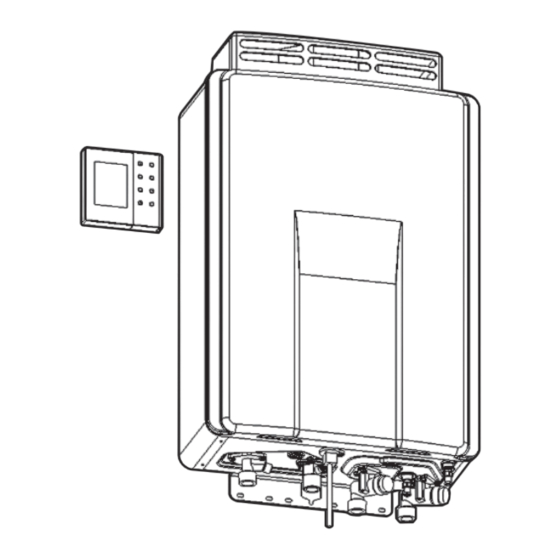
COMPONENTS & PARTS Remote Controller Exhaust Hood (Packed separately) Pressure Relief Valve (Drain Valve) Water Filter (Drain Valve) Drain Valve Hot Water Outlet Water Filter (Drain Valve) Gas Inlet Water Return Inlet Power Cord Cold Water Inlet... -
Page 3: Remote Controller
REMOTE CONTROLLER Remote controllers can be used in following combination. (3 controllers can be installed maximum) 1x main remote controller 1x main remote controller + 1x sub remote controller 1x main remote controller + 2x sub remote controller Main remote controller MC-195T-RS Priority display Time display Lock display... - Page 4 REMOTE CONTROLLER Sub remote controller MC-195-RS(Accessory) Priority display Time display Lock display Lock button Operation sign Shows current Light up when lock Press to turn Light up when When several clock time function is "on" on/off lock function operation is "on" controllers are installed, only the controller with this display can change Operation button temperature When you use hot water turn switch Preheat display "on" (Operation Light up when pre- sign on). When you heat operation is press the button "on" again it becomes "off". Temperature display Water temp button Display hot water deliver temperature Press to change ...
-
Page 5: First Time Use
FIRST TIME USE Follow below instructions before use Open water inlet valve fully Plug in Turn on hot water tap, make Open gas valve fully sure there is water flow, then turn off tap To avoid electric shock, don’t use wet hands to touch the power plug or socket. -
Page 6: How To Use
HOW TO USE Set clock time -- : --" when you turn on the controller without setting clock time. Display shows " Please set the clock following procedure below. Clock can be set by main remote controller (MC-195T-RS). Sub remote controller (MC-195-RS) cannot. - Page 7 HOW TO USE ● To prevent being scalded, check the water temperature by hand before shower. ● After using hot shower, some hot water will still remain in the water pipe. To prevent being scalded, check water temperature by hand Warning before use.
- Page 8 HOW TO USE Deliver hot water with opening hot water tap. ● During hot water delivery display shows "Combustion" display. Combustion display The actual water temperature varies depending on season and length of piping. Please take displayed temperature as rough indication. With small amount of water delivery, "Combustion"...
- Page 9 HOW TO USE How to use preheat function (continuous use) Preheat function is to circulate hot water through piping to keep it warm to deliver hot water immediately when you open tap. ※Use main controller (MC‐195T‐RS) Check operation sign(green) is on. When the operation sign doesn't light, press Operation "Operation"...
- Page 10 HOW TO USE How to use preheat function (with timer) Control by Main remote controller(MC‐195T‐RS) Before using timer function please check current clock time is correct. Without setting clock time, timer setting isn't shown even pressing timer button. Please press timer button after setting clock time. Operation Check operation sign (green) is on.
- Page 11 HOW TO USE How to use preheat operation (How to change timer setting) You can change the time by main remote controller (MC-195T-RS) In case changing "Timer setting 1" of Preheat "On" to "AM7:00 ~ 9:00 " and " PM6:00 ~ 12:00" Press "Timer"...
- Page 12 HOW TO USE Press "Preheat" button. "Off" display turns to "On" display. The step of "AM8:00 ~ 9:00" lights. Press "Function" button to finish the timer setting. "Timer 1" display lights and steps stop flashing. Unless pressing "Function" button, after 30 seconds timer setting finishes automatically.
- Page 13 HOW TO USE How to use lock function With lock function all buttons stop working to prevent small kids from doing mischief or wrong operation. Lock function can be used for both cases controller is "On" and "Off". In lock mode all operation buttons are blocked except lock button. Lock mode can be set by each controller.
- Page 14 HOW TO USE Press "Function" button once when remote controller is "On" and don't use timer. Display shows as below. Function number Setting mode Press "Up" or "Down" button to change to preferable mode. Saving mode 2 is preset in the factory. Mode Brightness Light off time...
- Page 15 HOW TO USE Press "Up" or "Down" button to change mode. Beep ON is preset in the factory. Mode Beep Beep Silence Press "Function" button twice to go back to original display. Unless pressing "Function" button after 1 minutes it goes back to the original display automatically.
-
Page 16: Safety Notes
SAFETY NOTES Outdoor water heater must not be installed indoor. If the unit is installed indoor, poor ventilation will cause incomplete combustion which leads to oxygen deficiency and CO toxication. Outdoor water heater must not be installed indoor. Check and clean exhaust outlet Check and clean Exhaust outlet regularly to prevent from blocking. - Page 17 " T r o u b l e Shooting". If product doesn’ t still operate properly, please contact Rinnai authorized service centre.
-
Page 18: Installation
INSTALLATION Accessories (included) After unpacking the appliance check for damage, if the heater is damaged or appears to have any defects contact your supplier immediately. DO NOT install a damaged appliance before checking with your supplier. Remove the accessories pack and the heater from the carton and check that all the parts are included. - Page 19 INSTALLATION Installation Precautions Please refer to data label to see if gas type, electric point and installation site is appropreate. Installation of the water heater requires expert qualification and technique. Please ask expertise for installation and make the unit installed correctly.
- Page 20 INSTALLATION Installation locations for the w a ter heater Please install the unit well venti- Please do not install near other lated outdoor place (ex. balcony, gas appliances.Please do not put rooftop) flammable gas or liquid around the unit. It is prohibited to install the unit ● Please do not install the unit un- ● indoor or inside of bathroom. de rn e ath of ve n tilation f an or cooker hood. Exhaust outlet of cooker hood Please install the unit where its noize ● or exhaust air do not bother neighbors.
- Page 21 INSTALLATION Water heater installation procedure 1. Remove exhaust hood. (Remove 4 screws) 2. Hole location: Hole on wall following water heaters dimension and instruction, and hammer in 5x φ8wall plugs. 3. Screw a wood screw into the wall plug which is on the middle of the top, until the distance between screw head and wall becomes 5mm.
- Page 22 INSTALLATION Water inlet/outlet and circulation piping To facilitate repair and maintenance, set a water inlet valve near the water inlet. Before connecting the water inlet pipe to the equipment, open the water inlet valve to flush out the dirt and debris in the water pipe. When the all pipes are connected to the equipment, wake to carry out the flushing test.
- Page 23 INSTALLATION The difference in height for circulation pipings should be within 5m. I n t h i s c a s e , m o r e t h a n 2 4 5 k P a (2.5kgf/cm ) is required for water inlet of within 5m within 5m the unit.
- Page 24 INSTALLATION Gas Connection Gas outlet In case there is no gas connection outlet where the unit is to be installed or in case gas outlet location or dimension is not appropriate, talk with gas companies for installation, relocation or replacement. The unit requires dedicated outlet.
- Page 25 INSTALLATION Trial operation Refer to p5 ~ p14 in manual after installing remote controller to do trial operation. After checking that the unit operates without any problem, explain the end user how to use the unit and pass this manual to him/her. 1....
-
Page 26: Remote Controller Installation
REMOTE CONTROLLER INSTALLATION Accessories (included) Following accessories are included in the package of remote controller. Check before instal- lation. Unit Unit Parts name, Shape Parts name, Shape 2 2 φ6 Wall plug M4×25 screw 2 4 φ4.1×25 screw Closed end connector 1 φ4×8 screw Cable clamp Accessories (not included) Following accessories are not included. If necessary you need to buy them separately. Parts name Model number Notes... - Page 27 REMOTE CONTROLLER INSTALLATION How to install remote controller (1 x main remote controller) Please do not install the unit at following places ・In bathroom or places with spray or steam (Controller is not waterproof) ・Places with high temperature or sunshine ・Places where oil scatters ・Ragged wall (Case can be distorted to cause failure) ・Places where some medicines are used (Benzene, Alcohol, extra...
- Page 28 REMOTE CONTROLLER INSTALLATION Insert remote controller connector Fix front panel using 4 screws and into the connector of unit and fix attach 2 decoration plates r e m o t e c o n t r o l l e r c a b l e w i t h bracket, using screws and cable clamp.
- Page 29 REMOTE CONTROLLER INSTALLATION Bring out duplex cable through the hole to connect with remote controller cable with Closed end connector. Peel off the trunking of each cable by 10mm before you crimp them. There is no polar character. Insert hooks of fixing plate into remote controller and move controller down until it clicks. Move downward In case of open wiring, remove cable outlet on remote controller case by nipper.
- Page 30 REMOTE CONTROLLER INSTALLATION Installation onto switch box Put fixing Plate onto switch box using Bring out duplex cable through the hole screws. (M4×25) to connect with remote controller cable with closed end connector. Peel off the trunking of each cable by 10mm before you crimp them.
- Page 31 REMOTE CONTROLLER INSTALLATION How to install remote controllers more than one controller Remote controllers can be used in following combination. (3 controllers can be installed maximum) ・1x main remote controller + 1x sub remote controller ・1x main remote controller + 2x sub remote controller Remove 2 decoration plates to Use closed end connector to crimp remove front panel (remove 4...
- Page 32 REMOTE CONTROLLER INSTALLATION Refer to p26 ~ p29 to install each Fix front panel using 4 screws and attach 2 decoration plates controller ●Connect remote controller and duplex cable as below Connect 2 remote controllers Connect 3 remote controllers Main remote Sub remote Main remote Sub remote...
-
Page 33: Trouble Shooting
Is gas pressure too low? ● ● If the product doesn’t still operate properly after the above inspections, then disconnect the main plug, insert again to restart the operation. If this doesn’t still solve the problem, please contact Rinnai service centre. -
Page 34: Error Messages
Rinnai service centre. ● When the screen of the digital monitor of the Operating controller is blank, disconnect the power plug and connect again, press power ON. If there is still no light, please call Rinnai service centre. -
Page 35: Inspection & Maintenance
Do not clean it with detergent, thinner etc. Do not remove it. ● In order to ensure safe operation, please take safety inspection every year. Please contact Rinnai service centre about regular inspections. Maintenance ● If there is oil stain on the surface of the product, clean it with Rotate water filter to the wet cloth. - Page 36 INSPECTION & MAINTENANCE In disuse for long term Draw off water from the unit in disuse for long term. ● This maintenance should be done after cooling down the unit since after operation water inside of the unit can be hot. To avoid electric shock, don't use wet hands to touch the power plug ●...
-
Page 37: Product Specification
PRODUCT SPECIFICATION Appliance type Forced exhaust domestic gas water heater Type B Model name REU-2024WP-RS Type of gas Town Gas(G110) Gas supply pressure 8〜20mbar Heat input Qn/Qm 38.9/2.9 Kw Useful output Pn/Pm 34.9/2.4kW (20/1.4L/min⊿25℃) 37〜55℃(MC-195T-RS) Temperature range 37〜50℃(MC-195-RS) External dimension (W)423×(H)661×(D)185 Weight 22.6kg Minimum water flow 2.2L/min(10kPa) Water pressure(Pw) 5bar R3/4” R3/4” Cold water R3/4” Hot water R3/4” Water return Power supply AC230V/50Hz Electric consumption Maximum water flow 24L/min Flame lod Flame failure Water flow sensor No water heating... - Page 38 PRODUCT SPECIFICATION Pump head Pipe resistance (example) Hot water:3/4×40m Water return:3/4×40m Circulating water amount (L/min)
-
Page 39: Dimensions
DIMENSIONS Unit (mm) POWER CORD (AC230V 50Hz) COLD WATER INLET(R3/4) GAS INLET(R3/4) HOT WATER WATER RETURN OUTLET(R3/4) INLET(R3/4) - Page 40 Rinnai Holdings (Pacific) Pte Ltd 61 Ubi Road 1 #02-20 & 21 Oxley Bizhub Singapore 408727 www.rinnai.sg Tel:6748 9011 Fax:6745 9240 U318-0900-RS×01 00 2015.11...
Need help?
Do you have a question about the REU-2024WP-RS and is the answer not in the manual?
Questions and answers