
Related Manuals for Sartorius QC35EDE-S


Summary of Contents for Sartorius QC35EDE-S
- Page 1 This document courtesy of: Data Weighing Systems, Inc. Contact Us For immediate assistance call 1-800-750-6842...
- Page 2 98648-009-86 i a l I n d u s t r h n o l o g Sartorius i n g T e c W e i g h QC Models Electronic Scale Operating Instructions for Standard QC Models and...
-
Page 3: Table Of Contents
Contents Page Page General View of the Scale Care and Maintenance 1– 0 1–42 Cleaning 1–42 Installation Instructions 1– 5 Safety Inspection 1–43 Zone 2/Class I, Division 2 Hazardous Areas/Locations 1– 8 Scale Operating Menu 2– 1 Changing Menu Code Settings 2– 1 Setting Up the Scale Accessing the Menu 2–... - Page 4 Page Page Utilities for Printouts Specifications 5– 1 or Data Transfer Accessories (Options) 5– 9 Data Output Parameter 2– 9 Index 6– 1 Auto Print 2– 9 Data Output at Supplement: Defined Intervals 2–10 Brief Instructions Data ID Codes 2–11 Card for insertion under the Automatic Output of the dust cover...
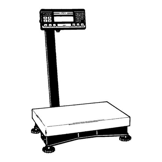
- Page 5 QC 7 Models Note: This illustration shows only the -L0CE model with raised display 1–0...
-
Page 6: Application Programs
No. Designation No. Designation 1 Display unit 15 Display for application programs 2 Power socket 16 i/i Info key 3 Load plate 17 c/c CF key 4 Leveling foot 18 e/o On/Off 19 S/a Totalization memory – 5 Retainers for the display unit 6 Clip 20 s/r Data output –... - Page 7 QC 34 and QC 64 Models RECALL/ STORE PRESET PRESET TARE TARGET ACCUM. ACCUM. RECALL AV.PIECE COUNT/ ON/OFF CLEAR INFO ZERO/TARE PRINT WEIGHT WEIGHT 1–2...
- Page 8 No. Designation No. Designation 1 Display unit 15 Display for application programs 2 Power socket 16 i/i Info key 3 Load plate 17 c/c CF key 4 Leveling foot 18 e/o On/off 19 S/a Totalization memory – 5 Retainers for the display unit 6 Clip 20 s/r Data output –...
-
Page 9: Transport Locking Device
Important Note to Users Make sure to carefully read and follow sections marked with this symbol – they contain important safety instructions. If you turn off the scale while it is running on power supplied by the battery pack and the external AC adapter YRB06Z is not plugged in for recharging, make sure to turn off the battery pack as well. -
Page 10: Installation Instructions
(see the section entitled “Accessories (Options)”). If you are interested in using your Sartorius QC scale for any other purpose, please contact your Sartorius Service Center. Sartorius does not accept any liability connected with the use of their scales for other than their intended purposes. -
Page 11: Storage And Shipping Conditions
Changes or modifications not expressly approved by Sartorius AG could void the user’s authority to operate the equipment. 1–6... - Page 12 Installation Ambient Conditions Sartorius QC scales are designed to provide reliable weighing and counting results under normal ambient conditions encountered in industrial environments. When choosing a location to set up your scale, observe the following so that you will be able to work with added speed and accuracy: –...
-
Page 13: Zone 2/Class I, Division 2 Hazardous Areas/Locations
(in Germany, according to DIN VDE 0165). For information on the legal regulations currently applicable in your country, please ask your Sartorius office or dealer. To install the power supply, please read the instructions in the section entitled “Getting Started.”... - Page 14 Any tampering with the QC equipment by anyone, other than authorized by Sartorius service technicians, will result in forfeiture of all claims under the manufacturer’s warranty! The QC scale along with an ING2 power supply is suitable for use in the following hazardous area...
-
Page 15: Qc7 Models
Setting Up the Scale – QC 7 Models: Carefully unpack the scale and accessories. Mounting the Display Unit on a Table or Wall (optional; order no. YDH01TS) – Remove the retainers (5) from the support arm – Remove the display unit –... - Page 16 – Unfasten the retaining plate from the back of the scale – Unwind the cable as far as required and then refasten the retaining plate Leveling the Scale Using the Level Indicator § Level the scale using the level indicator as a guide. $ Extend the leveling feet (turn clockwise) to raise the scale $ Retract the levelling feet (turn counterclockwise) to...
-
Page 17: Qc34 And Qc64 Models
– QC 34 and QC 64 Models: Carefully unpack the scale and accessories. Place the scale on a table and lay the support arm and display unit next to it. Always secure the transport locking devices before any transport of your scale. Unplug the scale from AC power and remove the load plate from the scale before changing the display mounting. -
Page 18: Mounting Options For The Display Unit
Mounting Options for the Display Unit Note: The following display mounting options apply to QC 34 and QC 64 models only. The display unit can be mounted as follows: – on the short side of the scale (see page 1–14) –... - Page 19 Mounting the Raised Display Unit on the Short Side of the Scale First, decide whether you want to mount the display on the short side or on the back (long side) of the scale. Please follow the instructions given on page 1–12 before you begin to change the display mounting.
- Page 20 Scale with the display unit mounted on the short side. Scale with the display unit mounted on the back (long side). Note: The cable routing will have to be changed, depending on the position of the display unit. 1–15...
- Page 21 Mounting the Raised Display Unit on the Long Side of the Scale Please be careful that the scale does not fall over when disassembling and mounting the parts as described here and in the following steps. Follow the instructions given on page 1–12 before you begin to change the display mounting.
- Page 22 Remove the screws on the retainer plate. Then set the scale back upright. Remove the screws on the base (7). Lay the support arm along with the base and the display unit on a table. Remove the plugs from the long side of the scale (insert them in the holes on the short side).
- Page 23 Refasten the retainer plate for the cable. Refasten the frame with the fastening screws. Refasten the base plate. Set the scale back upright and tighten the Allen screws on the base. Follow these steps if you need to change the display mounting again.
- Page 24 Mounting the Remote Display Unit (Option) (only possible with the optional display holder; order no. YDH01TS) Note: You can also mount the display as a remote unit for the QC 7 model. Please be careful that the scale does not fall over when disassembling and mounting the parts as described here and in the following steps.
- Page 25 Remove the screws on the base (7) (see diagram on the left). Then set the scale back upright. Remove the fastening screws. Lay the support arm along with the base and the display unit on a table. Unfasten the screws on the display unit (5) and remove the retainers.
- Page 26 Unwind the cable as far as required. Mount the display unit on the display holder using the retainers you previously removed. Now refasten the retainer plate for the cable. Set the scale back upright. 1–21...
-
Page 27: Getting Started
Getting Started Set the load plate (3) on the scale. Note: (For QC 34 and QC 64 models only) Transport Locking Device Set up the scale at the place of installation and remove the load plate. The transport locking devices (yellow) are located on the short sides of the scale. -
Page 28: Using The Scale In Legal Metrology
Sartorius. If the scale is moved, it must be verified again at its new location. In this case, the scale must be verified and stamp-approved at the new location by your local weights and measures office. -
Page 29: Connecting The Scale To Ac Power
If the voltage specified on the label or the plug design of the AC adapter do not match the rating or standard you use, please contact your Sartorius office or dealer. When you use the scale and associated equipment, you must comply with the national electrical code and applicable safety regulations of your country. - Page 30 The IP 65-protected ING-2 no. 69 71899 AC adapter is completely encapsulated and can be installed as a stationary unit. To use a main feeder cable from the ceiling or to mount a CEE plug, you will have to make arrangements.
-
Page 31: Safety Precautions
Use only original Sartorius AC adapters. Use of AC adapters from other manufacturers, even if these units have a registered approval rating from a national testing laboratory, requires the approval of an authorized Sartorius service technician. To operate the scale using an external rechargeable battery pack, see the section entitled “Accessories... -
Page 32: Connecting Electronic Peripheral Devices
Connecting Electronic Peripheral Devices Make absolutely sure to unplug the scale from the power supply before you connect or disconnect a peripheral device (e.g. printer, PC, etc.) to or from the interface port. If you use the QC scale in a Zone 2/Class I, Div. 2 hazardous area/location, the QC equipment must be completely disconnected from AC power before you connect or disconnect any cables to or from... -
Page 33: Leveling The Scale Using The Level Indicator
Installing a Drive-on Ramp (For the models FEP-I, IGP-I, FES-I und IGS-I) The drive-on ramp must be installed and put into operation by a trained Sartorius dealer or service technician. See the table in the “Accessories” list to order the drive-on ramp suited for use with your weighing platform. -
Page 34: Declaration Of Conformity
EU Member States through the implementation of the EC Directives adopted by the respective national laws. Sartorius complies with the EC Directives and European Standards in order to supply its customers with weighing instruments that feature the latest advanced technology and provide many years of trouble-free service. -
Page 35: Specifications
Important Note: The operator shall be responsible for any modifications to Sartorius equipment and for any connections of cables or equipment not supplied by Sartorius and must check and, if necessary, correct these modifications and connections. On request, Sartorius will provide information on the minimum operating specifications (in accordance with the Standards listed above for defined immunity to interference). - Page 36 Notified Body registered at the Commission of the European Community for performing such verification. The legal basis allowing Sartorius to perform EC verification is constituted by the EC Council Directive No. 90/384/EEC on non-automatic weighing...
- Page 37 Declaration of Type Conformity 1–32...
-
Page 38: Ec Type-Approval Certificate
EC Type-Approval Certificate 1–33... - Page 39 Sartorius office, dealer or service center. * in accordance with the accreditation certificate issued to Sartorius AG...
-
Page 40: Operating The Scale
Operating the Scale Turning the Scale On and Off Press the e/o key (18) to turn the display on and off. Self-Test When the scale is switched on, an automatic self-test of the scale’s electronic circuitry is performed. At the end of the self-test, a zero readout is displayed. This means that the scale is ready for use. -
Page 41: Simple Weighing
b means Busy Once you turn on the scale, the b symbol is displayed until you press a key. During operation, this symbol indicates that the scale is still busy processing a function and will not accept another command to perform any other functions at this time. -
Page 42: Calibration/Adjustment
You can find an overview of the calibration weight sets available in the section entitled “Accessories (Options).” You need an exact calibration weight. Type QC7CCE-S QC34EDE-S QC64EDE-S Weight (g) 1x 5,000 1x10,000 2x10,000... - Page 43 When a zero readout is displayed, press the =/z key (14). This starts calibration. The calibration weight is displayed in grams. Errors or interference at the start of the calibration routine are indicated by the error code “Err 02.” If this is the case, tare and press the =/z key again when a zero readout appears.
-
Page 44: Data Interface
Data Interface If you wish to record weighing data using a Sartorius Data Printer, plug the YCC01-0016M3 data cable into the interface port (28) of the scale. You do not need to adjust any settings! Connecting Electronic Peripheral Devices Make absolutely sure to unplug the scale from AC power before you connect or disconnect a peripheral device (printer or PC) to or from the interface port. -
Page 45: Interfacing Devices With The Scale
Note: If you use the QC scale in a Zone 2/Class I, Div. 2 hazardous area/location, the QC equipment must be completely disconnected from AC power before you connect or disconnect any cables to or from the equipment. The same applies to all accessories operated with the system. -
Page 46: Troubleshooting Guide
Troubleshooting Guide Problem Causes Solution No segments – No AC power is available – Check the AC power appear in the weight supply display (1) – The AC adapter is not – Plug in the AC adapter plugged in The weight display –... -
Page 47: Care And Maintenance
Care and Maintenance Service Regular servicing by a Sartorius service technician will extend the service life of your scale and ensure its continued weighing accuracy. Sartorius can offer you service contracts, with your choice of regular maintenance intervals ranging from 1 month to 2 years. -
Page 48: Safety Inspection
Safety Inspection If there is any indication that safe operation of the scale with the AC adapter is no longer warranted, turn off the power and disconnect the equipment from AC power immediately. Lock the equipment in a secure place to ensure that it cannot be used for the time being. -
Page 49: Scale Operating Menu
Scale Operating Menu Changing Settings in the Scale Operating Menu In the operating menu, you can define how your scale will adapt to ambient conditions and also how it will work to meet your special requirements. The factory settings of the scale operating menu are identified by an “*”. You can select the functions not identified by an “*”... -
Page 50: Accessing The Menu
Accessing the Menu – Press e/o (18) to turn off the scale. Turn the scale back on. – While all segments are displayed, briefly hold down the =/z key (14). – Release when “1” (“–C–”) is displayed. Note: If you use the scale as a legal measuring instrument, the “external calibration”... -
Page 51: Undoing All Menu Code Changes - Reset Function
Important Note: Changes to the code settings are not stored if you turn off the scale by pressing e/o while selecting the code numbers or before saving a setting. The current menu setting in the scale operating menu is identified by a small, superscript “o” after the last number. -
Page 52: Scale Operating Parameters
Scale Operating Parameters Adapting the Scale to Ambient Conditions The scale can be adapted to the prevailing ambient conditions at the place of installation. Code Changes Very stable conditions Stable conditions Unstable conditions Very unstable conditions Standard Weighing Mode – Manual Filling Mode You can optimally adapt your scale to meet either of these requirements. -
Page 53: Stability Symbol Delay
Stability Symbol Delay This setting allows your scale to compensate for individual interfering factors which slowly subside. You will not need to make any changes in this code setting, as a rule. Code Changes No delay Short delay Long delay Extremely long delay Tare Parameter You can define when the scale will perform the taring operation. -
Page 54: Calibration/Adjustment And Linearization Functions Using The E/O Key
Calibration/Adjustment and Linearization Functions Using the =/z Key (hold down key for more than 2 seconds) Important Note: For verifiable scales used as legal measuring instruments the menu access switch is blocked and sealed. The external calibration is not permitted. External Calibration and/or Linearization The weights to be placed on the scale for linearization are indicated in the display one after the other, in increasing order. -
Page 55: Weight Units
Weight Units Note: For verified scales approved for use as legal measuring instruments all weight units except g/kg are blocked. Code*** Symbol Conversation factor Code Changes 1 g = User-definable unit Grams Kilograms 0.001 3 ** Carats Pounds 0.0022046226 Ounces 0.035273962 Troy ounces 0.032150747... -
Page 56: Interface Parameter Settings
Interface Parameter Settings Baud Rate Code Changes 150 baud 300 baud 600 baud 1,200 baud 2,400 baud 4,800 baud 9,600 baud 19,200 baud Parity Code Changes Mark Space Even Number of Stop Bits Code Changes 1 stop bit 2 stop bits Handshake Mode Code Changes... -
Page 57: Data Output Parameter
Utilities for Printouts or Data Transfer Sartorius QC scales come standard with an interface. You can plug a Sartorius printer or a computer into this interface port. In addition, you can choose to have data output from your scale to this on-line device either automatically or by pressing the p/p key. -
Page 58: Data Output At Defined Intervals
Data Output at Defined Intervals You can reduce the volume of data in the “auto print” mode by defining the interval at which data will be output automatically. This auto print interval is based on the number of display updates. Auto print interval Code Changes... -
Page 59: Data Id Codes
Data ID Codes To help you identify weights, piece counts, percentages, etc., a code letter is printed or displayed in front of these values. If you set the code for “without data ID code,” only net weights, results in percent and counting results will be output. -
Page 60: Printout/Record Configuration
Depending on the menu code settings you select, you can have the weighing data output from your scale to a Sartorius printer (e.g. the YDP 03-0CE) or to an on-line computer. The data that is output also depends on the code settings. -
Page 61: Data Record Output
You can assign a fixed identification (third header line) of up to 6 characters to precede the 14-character identifier described above. This ID can be entered through an on-line computer, or by a Sartorius service technician. The on-line computer can also receive data from the scale. By connecting a printer, you can print the data received in the computer. - Page 62 This information can be entered through an on- line computer, or by a Sartorius service technician. The on-line computer can also receive data from the scale. By connecting a printer, you can print the data received in the computer.
- Page 63 Output of “wRef” and “nRef” Automatic output of the average piece weight, “wRef,” and the reference sample quantity, “nRef”: Your scale calculates the average piece weight from the number of parts loaded and the weight of the pieces; the calculation begins when you press the u/w key.
-
Page 64: Menu Access Function
Additional Functions Menu Access Function You can define the function of the menu access switch by setting the code for the scale operating menu to “accessible.” In this setting –C– (change) will be displayed on your scale whenever you access the menu. This means that you can change the menu codes any time regardless of the setting of the menu access switch. -
Page 65: Universal Switch For Remote Control
Universal Switch for Remote Control You can connect an external universal switch to the interface of your scale for remote control of certain functions listed below. Set the appropriate menu code to define the function of this switch. External key pad function Code Changes p/p key (11) -
Page 66: Display Backlighting
Display Backlighting Depending on your individual workplace requirements, you can turn the display backlighting on or off. Display backlighting Code Changes Automatic shut-off after 2 minutes If you select “Automatic shut-off after 2 minutes,” the display will shut off automatically after 2 minutes. If the displayed weight value does not change after 1 minute, the “b”... -
Page 67: Changes – Reset Function
Undoing All Menu Code Changes – Reset Function This function enables you to reset all menu codes back to the original factory settings, which are identified by an “*” in this manual. This can be very useful, for instance when you are not sure what changes have been made in the code settings. - Page 68 The settings required to run the program and to generate documentation are given in a code table at the beginning of each example. Your Sartorius scale can help you in counting parts, totalizing values, checking or storing the weight of parts or of a piece count.
- Page 69 Insertable Instruction Cards for the Dust Cover In the pocket at the back of this manual, you will find a sheet of instruction cards for various applications. Detach the cards of your choice and insert them in the pockets provided in the dust cover. These cards will make it easy for you to operate the scale.
- Page 70 Programs (Applications) Counting (page 3–4) Counting using your choice of reference piece count or reference weight. Tare Memory (page 3–13) Storing weighed values or numeric-key input of a weight with simultaneous subtraction of the stored value from the displayed value (subtraction of container weight).
- Page 71 Counting Counting Code 2 1 4* u/w key Symbol displayed: The counting program allows automatic conversion of weights into piece counts based on a reference sample quantity and weight. A weight readout is stored as a reference sample quantity (factory setting: 10 pcs = pieces). General Functions in the Counting Program Function/Application Entry Mode...
- Page 72 Changing the Reference Sample Quantity “nRef” You can change the reference sample quantity in cycles by pressing g/W key. Use the number keys 0 –9 and the u/w key to enter piece counts. Choose from the following settings for the reference sample quantity: 5, 10, 20, 50, 100 and a user-definable number (factory setting: 999).
- Page 73 Simple Counting The QC counting program is set at the factory so that you can begin counting without changing any settings. If you want to change the factory-set reference sample quantity, press g/W (13) to select one of the settings (5, 10, 20, 50, 100 or user-definable quantity –- this latter setting has been factory-set to 999*.
- Page 74 Storage of Reference Weight To determine and optimize the reference weight “wRef” you can choose whether the weight calculated is stored according to the display accuracy, or with full accuracy according to the internal resolution. If you select the higher internal resolution you can choose whether the internal resolution is 10-fold or 100-fold that of the display accuracy.
- Page 75 Criterion for Storage of Sample Weights and Tare Values (Only necessary with very low piece weights) To ensure that the calculation of the reference weights is as accurate and thus as reproducible as possible, you can set the scale for “increased stability.” This means that the weight stored is even more precisely calculated, which means the reference weight is also more precise.
- Page 76 There are 3 different ways you can then re-start the counting process: 1. Press u/w again. The weighed value for calculation of the reference weight will now be stored with a longer weighing time and “increased stability.” 2. Empty the container and place it on the scale again. Press =/z or o/t.
- Page 77 Reference Sample Updating After pressing u/w to start the counting application, you can change the reference sample quantity as desired. You either can update the reference sample quantity manually, by pressing u/w, or have it updated automatically during the counting process. Automatic reference sample updating is practical as long as the reference sample quantity is lower than 100 pieces.
- Page 78 Practical Example: Simple Counting The QC Counting Scale is set at the factory so that you can begin counting without changing any settings. Step/Key Display Data Output Place the container on the scale, press =/z (14) to tare Place the appropriate number of pieces (e.g.
- Page 79 Practical Example: Changing the Reference Sample Quantity Using the 0 – 9 Numeric Keys You are working in the Counting application, with a reference sample quantity of 10 pieces. Step/Key Display Data Output Remove the 10 pieces from the container and place the empty container back on the weighing pan.
-
Page 80: Tare Memory
Tare Memory Tare Memory Code 2 2 2* o/t key Symbol displayed when a value is stored: Press o/t key to store the tare weight. The balance is now automatically tared so you can weigh again starting with a zero readout. If you have stored a value in the tare memory, a “1”... - Page 81 Tare Memory Code Changes Tare memory blocked Tare memory Tare memory – automatic Practical Example: Auto-Container Tare – Net – Gross Step/Key Display Data Output 0.0 g Place the lightest-weight container you are working with on the weighing pan 149 g and press o/t key 0.0 g Remove the container...
- Page 82 Totalizing Totalizing Code 2 7 2* S/a key Read Totalizing Memory Σ Symbol displayed: With the totalizing application you can totalize weighed values and piece counts, whereby the total value displayed can exceed the capacity of the scale many times over. General Functions in the Totalizing Program: Function/Application Entry Mode...
- Page 83 If you have selected “Automatic Output of Totalizing Application Data” in the scale operating menu, you can document both the individual weights totalized and the total of all weights when weighing individual samples. Data output is generated automatically each time you press the S/a key. Data Output Transaction counter (1, 2, 3 etc.) n Net value...
- Page 84 Σ Practical Example: Totalizing Symbol displayed: Code 2 7 2* Symbol displayed: Code 2 1 4* and “Counting” Totalizing S/a key Read Totalizing Memory s/r key User guide display when you press i/i key + s/r key: S–n, S–t, S–b, S–C Application: Totalizing bulk parts of equal weight or weight values, whereby the total value displayed can exceed the capacity of the scale many times over.
- Page 85 Step/Key Display Data Output Remove container with pieces – 4 pcs Remove pieces from the container Place the empty container on the scale Place the empty container on the scale 0 pcs Place pieces in the container 20 pcs Press the S/a key to store the value in the totalizing memory Transaction counter 2...
- Page 86 Step/Key Display Data Output The residual sum can be filled to ...70 pcs 70 pcs Press the S/a key briefly; the residual sum is totalized 8.6 g Press the s/r key to output the contents of the totalizing memory Number of partial values Total sum net Sum-N + 61.1 g...
- Page 87 Over/Under Checkweighing For checkweighing, you can choose between two different programs: Checking net weights Code 2 6 2* z/T key Checking variations in weight z/T key Code 2 6 +/– Symbol displayed: Checking net weights and checking variations in weighed values or calculated values, with analog display as visual aid.
- Page 88 Function/Application Entry Mode User Data Guide Output Display i/i key + Display and p/p key + print information: Setp Target weight z/T key S – Min weight value Max weight value Tolerance ranges when values entered via keypad: d – d min Delta min d max...
- Page 89 Press the z/T key key to start the “Over/Under Checkweighing” application. The tolerance limit symbol flashes in the bar graph. The user guide display shows “SET”. Enter your target value and values for the lower tolerance limit “S – –” and the upper tolerance limit “S –...
- Page 90 Data Output Code Changes Triggering the Control Lines for the YRD11Z Checkweighing Display** You can use the Sartorius Three-Segment Checkweighing Display Unit, model YRD11Z, as a visual aid during checkweighing. For pure checkweighing applications, the external checkweighing display unit is recommended.
-
Page 91: Checking Net Weights
Checking Net Weights Checking net weights z/T key, user guide display shows: Set, S–, S+ Code 2 6 2* +/– Practical Example: Check weight Symbol displayed: Application: Checking the weight of bulk parts of identical weight; e.g. checking packages of screws where the packages have the same weight, checking the fill quantity, sorting. - Page 92 Step/Key Display Data Output Enter the tolerance values (e.g.1 g) using the numeric keys .0 g 1.0 g Press the z/T key again 100.1 g An acoustic signal is given (beep tone) and the data output is generated automatically. Setp 100.1 g d-min - 1.0 g...
- Page 93 Use in Combination with Other Programs +/– Practical Example: Checking Piece Count Symbol displayed: and “Counting” symbol: Application: Checking the piece count of bulk parts of identical weight; e.g. checking packages of screws where the packages must have the same weight; checking the fill quantity; sorting. Menu codes used in the example: Function Code...
- Page 94 Step/Key Display Data Output Enter the tolerance value (e.g.1 piece) using the numeric keys 10 gcs 1 pcs Press z/T key again to store the value 200 pcs The user guide display shows S–t = d – max. weight 200 pcs Enter the tolerance value (e.g.
-
Page 95: Checking Variations In Weight
Checking Variations in Weight Checking Variations in Weight z/T key, user guide display: dif, d –, d + Code 2 6 3 Note: Press the z/T key to toggle between LL, HH, variations and net value. Practical Example: Checking the Variations in Weight by Piece Count +/–... - Page 96 Step/Key Display Data Output The user guide display shows S– – = d – min. weight 200 pcs Enter the tolerance value (e.g. 1 piece) using the numeric keys 10 gcs Press the z/T key again 100.1 pcs The user guide display shows S–t = d –...
- Page 97 Individual Data ID Code Individual Data ID Code Code 2 8 2* d/d key You can enter up to 14 digits, or 13 digits plus a decimal point, using the numeric keys. The display shows a maximum of 7 digits. The number entered is stored in non-volatile memory.
- Page 98 ID function Code Changes Blocked Accessible Example: Storing ID Data Enter using numeric keys 0 –9 (max.14 digits) + d/d key (store). Printout p/p key The ID code designates: Current date and time, from printer 30-JAN-95 16:52:32 (only with YDP03-0CE) First header line –...
- Page 99 Memory Memory Code 2 9 2* r/s key Start Memory Function r/s key – press briefly Store Data using the Memory Function r/s key – press and hold +/– Symbol Displayed: flashes in the display. Note: The flashing symbol indicates the application you are currently working in and the values you can store.
- Page 100 Function/Application Entry Mode User Data Guide Output Display Load the value stored in Memory position 1 to 25 + r/s key a memory position: – press briefly Reference value “wRef” = Ref – Tare Tare value = Tare Target weight = Set Free Free memory = Free c/c key...
- Page 101 Memory With the memory function accessible, there are 25 memory locations available that you can use to store individual tare values, reference values for the counting function, or checkweighing limits. ID memory function Code Changes Blocked Accessible Practical Example: Storing Values in Memory Start an application program: Either counting, tare memory, or over/under checkweighing Step/Keys...
- Page 102 Memory Table Memory Application Abbreviation Value Example: Tare memory 100 g 3–35...
- Page 103 Error Codes in the Applications Your Sartorius Counting Scale comes equipped with an automatic function- monitoring feature. In case of function errors, error codes are shown in the main display and output to the port until the error is corrected.
-
Page 104: General Description Of The Data Interface
If you interface an original Sartorius accessory, such as a Sartorius Data Printer or a similar unit, with a scale that has the factory-set menu codes, you do not need to change any settings. -
Page 105: Handshake Mode
General Specifications Type of interface Serial point-to-point connector Operating mode Asynchronous, full-duplex Standard V28, RS-232C specification Handshake mode*) 2-wire interface: via software (XON/XOFF) 4-wire interface: via hardware handshake lines with Clear To Send (CTS) and Data Terminal Ready (DTR) Transmission rates*) 150;... -
Page 106: Data Output Formats
Data Output Formats Depending on the menu code setting: 7 2 1 = without data ID code or 7 2 2 = with data ID code data will be output with either 16 (code 7 2 1) or 22 characters (code 7 2 2). For a data output of 22 characters, a 6-character ID precedes the 16 characters reserved for the weight or other value. - Page 107 When data are output without decimals, the decimal point is suppressed (except when a certain display mode is selected). 10 11 12 13 14 15 16 – – – – – – – – – – – – – – – – – – – – – * 10 –...
-
Page 108: Index
Special Codes Special codes are output only if the scale operating menu code 6 11, 6 1 4 or 6 1 5 is set (see the section entitled “Data Output Parameter”). Special status-dependent codes 10 11 12 13 14 15 16 The following status codes are output for “A B”: * * : Tare H * : Overload... - Page 109 Data Output with ID Code When data with an ID code is output, the ID code consisting of 6 characters precedes the data with the 16-character format. During data output, all characters are shifted to the right by 6 places. 22nd character C C C C C C V * x x x x x x x x * U U U CR * * * * * *...
-
Page 110: Data Input Formats
Data Input Formats Commands can be input via the scale interface port to control the scale functions. Control commands with upper-case letters or special characters are distinguished from those with lower-case letters. Format for Control Commands Each character must be transmitted with a start bit, a 7-bit ASCII-coded character, a parity bit, and one or two stop bits. -
Page 111: Interface Commands
Interface Commands Control Commands with Upper-Case Letters The command <ESC> <S>, for example, causes the processor to reinitialize (turns the scale off and back on again). The scale will operate according to the commands available up until the processor is reinitialized. Once the scale has been turned on, the processor will always recognize the codes entered by the user in the scale operating menu. - Page 112 Command: Function ESC f0 g/W key – Toggle betw. weighing/counting, or betw. ref./pc. ct. ESC f1 o/t key – Store in tare memory ESC f2 u/w key – Start – counting ESC f3 z/T key – Start – checkweighing ESC f4 S/a key –...
-
Page 113: Basic Program
1000 ON ERROR GOTO 10000 1010 CLS 1011 PRINT “Enter the fixed 2-line header and ID label” 1012 “Sartorius QC Series Counting Scale with PC Connecting Cable (1200Bd,O,7,1)” 1013 INPUT “Your PC interface, i.e. COM1 or COM2 (enter 1 or 2)”; a 1015 IF a = 1 THEN OPEN “com1:1200,o,7,1,CS1000,DS0,CD0,PE”... - Page 114 2150 PRINT #1, CHR$(27); “P”: REM Pass print command to QC 2160 REM Catch output; dum$ catches Date/Time command 2161 INPUT #1, dum$, e1$, e2$, e3$, e4$ 2162 CLOSE #1 2170 LOCATE 19, 4: PRINT e1$: LOCATE 20, 4: PRINT e2$: LOCATE 21, 4: PRINT e3$ 2500 LOCATE 22, 4: PRINT “...in the QC...
- Page 115 Numeric Input x = Any number which may include a plus or minus sign; can have anywhere from 1 to 7 places . = Decimal point: “.,” or “_”= underline (ASCII = 95) The numeric value may not have more than 7 digits (excluding the decimal point). Each control command with the lower-case letters f, s, t, x and z must be terminated by an underline (ASCII = 95).
-
Page 116: Synchronization And Data Output Parameters
In this case, data will be output but not received. Handshake The scale interface (Sartorius Balance Interface = SBI) has a 23-byte transmit buffer and a 40-byte receive buffer You can access the scale operating menu to define various handshake parameters: Software handshake: controlled by “XOFF”... - Page 117 For data communication with a software handshake, “XON” must be sent by a device when it is turned on in order to enable another online device to exchange data. Sequence: Scale Receiving device – – – – – byte – – – – → –...
- Page 118 Activating a Data Output Process You can define the data output parameter so that output is activated either automatically or when a print command is received. You have two options for the automatic mode: data output can be either synchronous with the scale display or activated at defined intervals (to select the parameter, see “Utilities for Printouts or Data Transfer”).
-
Page 119: Interface Parameter Settings
Interface Parameter Settings Utilities Data output- Print interval after Code Changes parameter Code Changes 1 disp.update 6 3 1 * W/o stability 6 1 1 2 disp.updates 6 3 2 After stability 6 1 2 * 5 disp.updates 6 3 3 At stability 6 1 3 10 disp.updates... - Page 120 Control Lines When using the “over/under checkweighing” application program, you can use the voltage level of four data output port lines to control an external online display or control instrument. The voltage levels of the data output ports will change according to various patterns, depending on the reference weight limit and on the lower and upper weight limits.
- Page 121 Pin Assignment Chart for 12-pin Round Connector Interface Connector: Round connector (TXD) send (RXD) receive (DTR) (CTS) (SGN GND) Signal IP65 circular ring 25-pin (with DB25-scale 12-pin adapter cable) > SGND 7, 8, 14 +5 V 13, 25, 12 < Universal switch +12 V ensure a low-ohm connection between shielding and plug housing...
-
Page 122: Cabling Diagram
Note for use with commercially available RS-232 cable: RS-232 cables purchased elsewhere often have pin assignments that differ from those of Sartorius connecting cables. Always check the cabling diagrams of the equipment used before installation, and disconnect any lines that have inappropriate assignments (e.g. pin 6). - Page 123 Pin Assignment: Pin 1: Shield Pin 2: Data Output (TxD) Pin 3: Data Input (RxD) Pin 4: Not Connected Pin 5: Clear to Send (CTS) Pin 6: Internally Connected Pin 7: Internal Ground (GND) Pin 8: Internal Ground (GND) Pin 9: Not Connected Pin 10: Not Connected Pin 11: +12 V Pin 12: +5 V Connection for a switch...
- Page 124 Cabling Diagram (Adapter cable – YCC03ISM5 – round – DB25-PC) Diagram for interfacing a computer or a peripheral device to the scale using the RS-232C/V24 standard and interface cables up to 15 m (50 ft) long. Cabling Diagram Connection assignments for the cable from the QC scale to an RS-232 PC interface. Round plug 12-pin 25-pin Scale cable...
- Page 125 Scale Female connector 25-pin 9-pin Buchse 25 pol oder 9 pol 4–22...
- Page 126 Specifications Model QC34EDE-S QC64EDE-S Weighing range structure Readability ≤±1 ≤±2 Reproducibility (standard deviation) ≤±1 ≤±2 Linearity ≤1.5 ≤1.5 Response time (average) Model QC7CCE-D QC34EDE-D QC64EDE-D Weighing range I 0.72 Weighing range II Readability range I 0.01 Readability range II ≤±0.2 ≤±1...
- Page 127 Model QC7CCE-L0CE QC34EDE-L0CE QC64EDE-L0CE Type DI BG 300 DN BG 300 DI BG 300 Accuracy class Weighing range Readability/scale interval d* Verification scale interval e* Minimum capacity Selectable weight units g, kg Operating temperature range °C –10°C … +40°C Standard models (non verifiable) with stainless steel load plate Model QC150IGP-I QC300IGP-I...
- Page 128 5–3...
- Page 129 Model QC7DCE-S QC15DCE-S QC35EDE-S QC60FEG-S Weighing capacity Readability Repeatability (standard deviation) ±0.2 ±0.4 ±1 ±2 Linearity ±0.2 ±0.6 ±1.5 ±4 ≤1.5 ≤1.5 ≤1.5 ≤1.5 Response time (average) Load plate size 320 x 240 320 x 240 400 x 300 500 x 400 Model QC65EDE-S QC150FEG-S...
- Page 130 General Specifications Load capacity (models QC 7, 35, 65) 14 kg 70 kg 130 kg Display update (depends on the filter level selected) and data printout/ record rate interface 0.1– 0.4 Ambient temperature range* 273...313 (0...+40°C) Operating temperature range* °C 10°C–30°C ≤±6 ·10 ≤±10 ·10...
- Page 131 Dimensions (Scale Drawings) QC7DCE models QC34EDE-S, QC64EDE-S, -D, -P and -S0CE/-L0CE models Note: All dimensions in millimeters. 5–6...
- Page 132 For painted scales: QC150IGP-I, QC300IGP-I and -L0CE models For stainless steel scales: QC60FES-I, QC150FES-I and -L0CE models Note: All dimensions in millimeters. 5–7...
- Page 133 Dimensions (Scale Drawings) For painted scales: QC150IGP-I, QC300IGP-I and -L0CE models For stainless steel scales: QC150IGP-I, QC300IGS-I and -L0CE models Note: All dimensions in millimeters. 5–8...
- Page 134 Accessories (Options) Data Printer YDP 03-0CE* with date/time, statistical evaluation of data; Print speed approx. lines/sec. Printer pan size (W x D x H) in mm 150 x138 x 43 Paper rolls, 5 units, 50 m each/ 69 06937 164 feet (spare part) paper rolls, 5 units, 14 m each/ 69 06920 50 feet (spare part)
- Page 135 Table AC adapter 6971899 (IP-65 protection) ING-2 Gasket for AC plug, secondary 6971915 (spare part) Foot screw (QC7CCE-S) (spare part) 69QC0004 Foot screw (QC34EDE-S, 69QS0054 QC64EDE-S) (spare part) 3 segment external checkweighing display RED – GREEN – RED YRD 11Z* incl.
- Page 136 YCW 7138-00 QC35EDE-P 1 x 10 YCW 7138-00 QC60FEG-S** 2 x 10 YCW 7138-00 QC65EDE-D** 2 x 10 YCW 7138-00 QC65EDE-S** 2 x 10 YCW 7559-00 QC150-FEG-S** 1 x 50 ** Sartorius offers you external calibration service for your equipment. 5–11...
- Page 137 (only for models QC34EDE-S and QC64EDE-S) For further information about the use of your scale and/or the spare parts, please contact one of our local Sartorius service center, office or dealer. * Only in combination with adapter cable YCC01-0016M3 5–12...
- Page 138 Index Page Page AC power connection Important note to users 1–24 1–4 Accuracy test 3–8 Installation 1–7 Ambient conditions 1–7 Interface commands 4–8 Anti-theft device 1–9 Interface parameters 4–16 Application parameters 2–10 Interfacing devices ASCII characters 4–12 with the scale 1–40 Auto print 2–9...
- Page 139 Page Stability range 2–4 Storage and shipping 1–6 Synchronization 4–13 Tare memory 3–13 Totalizing 3–15 Transport locking device 1–22 Universal remote switch 2–17 Warranty 1–5 6–2...
- Page 140 WQC6002-e99045 Brief Instructions for QC Counting Scales Key Functions Simple Weighing – Press =/z to zero the Function display Turns the scale on and off – Press =/z or o/t Clears functions to tare the container on the pan Information –...
- Page 141 Setting a Menu Code Turn off the scale; then turn it back on. While all segments are displayed, briefly hold down =/z. “1” and “-C-” appear in the user guide display. (If “-L-” appears, set the menu code 8 1 1.) To select a menu code, press u/w (increases a number in increments) and p/p (advances to the next number).
- Page 142 Adjustment/Calibration/Linearization Press =/z and hold External adjustment/ for 2 seconds: calibration (code 1 9 1) External linearization (code 1 9 5) Unload weighing pan. Tare the scale. Press =/z: 0.0 g or 0 kg. Place required weight on the pan: 5 kg/10 kg (for the required weight, see “Specifications”...
- Page 143 Menu Code Settings at a Glance These charts summarizing the menu parameters are intended to give you a quick-reference guide. The most important menu codes for the weighing mode: Stability symbol delay Code Weight units Amb. conditions Code Very stable 1 1 1 No delay 1 4 1...
- Page 144 Display Modes Application Programs Totalizing Code Counting Highest possible Code Code S/a and u/w key blocked accuracy 1 8 1* 2 1 1 keys blocked 2 7 1 Last numeral blanked Counting 2 1 4* Totalizing 2 7 2* when load changes 1 8 2 Tare memory Code...
- Page 145 Accuracy test Forced print when S/a Data Interface Code is pressed Baud rate Code None Code (min. load 1 increment) 3 10 1* Printout is output 3 13 1 150 baud 5 1 1 300 baud 5 1 2 99.0% ( 100 incr.) 3 10 2 Blocked 3 13 2*...
- Page 146 Utilities Record Header (Your Co. Name) Auto tare when Data output Code Output of header lines 1 and 2 S/a is pressed 6 4 3 Code W/out stability 6 1 1 No output 7 5 1 After stability 6 1 2* Output of Application Output 1st header line 7 5 2...
- Page 147 Universal Switch Line Feed Code Display Backlighting Code Code No line feed 7 8 1 p/p key 8 4 1* 8 6 1 Line feed – 1 line 7 8 2 8 6 2 =/z key 8 4 2 Line feed – 2 lines 7 8 3 Auto shut-off after 2 min 8 6 3*...
- Page 148 All rights reserved. No part of this publication may be reprinted or translated in any form or by any means without the prior written permission of Sartorius AG. The status of the information, specifications and illustrations in this manual is indicated by the date given below.
Need help?
Do you have a question about the QC35EDE-S and is the answer not in the manual?
Questions and answers