Yamaha PianoCraft NX-E800 Service Manual
Hide thumbs
Also See for PianoCraft NX-E800:
- Owner's manual (548 pages) ,
- Specifications (2 pages) ,
- Specifications (2 pages)
Table of Contents
Advertisement
MICRO COMPONENT SYSTEM
RX-E810/RX-E410/
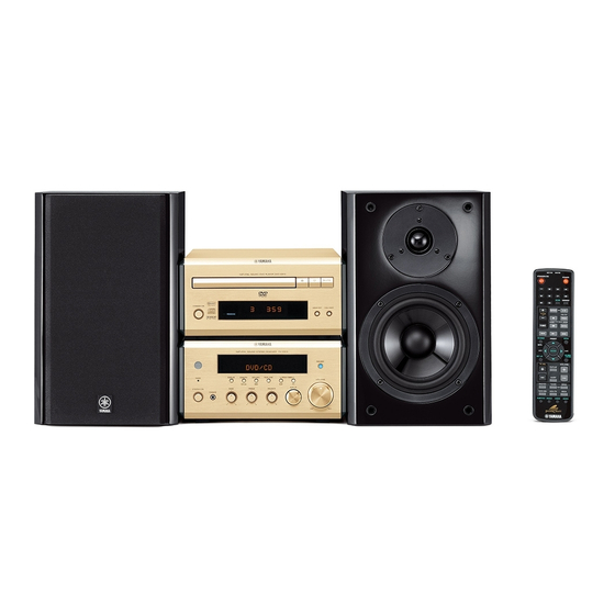
The MCR-E810 is composed of the RX-E810, NX-E800 and DVD-E810.
The MCR-E410 is composed of the RX-E410, NX-E800 and CDX-E410.
This service manual is for the RX-E810, RX-E410 and NX-E800.
For service manual of the DVD-E810 and CDX-E410, please refer to the following publication number:
This manual has been provided for the use of authorized YAMAHA Retailers and their service personnel.
It has been assumed that basic service procedures inherent to the industry, and more specifically YAMAHA Products, are
already known and understood by the users, and have therefore not been restated.
WARNING:
IMPORTANT:
The data provided is believed to be accurate and applicable to the unit(s) indicated on the cover. The research, engineering,
and service departments of YAMAHA are continually striving to improve YAMAHA products. Modifications are, therefore,
inevitable and specifications are subject to change without notice or obligation to retrofit. Should any discrepancy appear to
exist, please contact the distributor's Service Division.
WARNING:
IMPORTANT:
I CONTENTS
To Service Personnel . . . . . . . . . . . . . . . . . . . . 2
System Composition . . . . . . . . . . . . . . . . . . . . . . 3
Front Panels . . . . . . . . . . . . . . . . . . . . . . . . . . . . . 4
Rear Panels . . . . . . . . . . . . . . . . . . . . . . . . . . . . 4–6
Remote Control Panels . . . . . . . . . . . . . . . . . . 6
Specifications . . . . . . . . . . . . . . . . . . . . . . . . . . . . 7
Internal View . . . . . . . . . . . . . . . . . . . . . . . . . . . . . 8
Disassembly Procedures . . . . . . . . . . . . . . . . . 8
Self Diagnosis Function (Diag) . . . . . . . . . 9–15
Amp Adjustments . . . . . . . . . . . . . . . . . . . . . . . . 16
1 0 1 0 1 9
DVD-E810
CDX-E410
IMPORTANT NOTICE
Failure to follow appropriate service and safety procedures when servicing this product may result in per-
sonal injury, destruction of expensive components, and failure of the product to perform as specified. For
these reasons, we advise all YAMAHA product owners that any service required should be performed by
an authorized YAMAHA Retailer or the appointed service representative.
The presentation or sale of this manual to any individual or firm does not constitute authorization, certifica-
tion or recognition of any applicable technical capabilities, or establish a principle-agent relationship of
any form.
Static discharges can destroy expensive components. Discharge any static electricity your body may have
accumulated by grounding yourself to the ground buss in the unit (heavy gauge black wires connect to this
buss).
Turn the unit OFF during disassembly and part replacement. Recheck all work before you apply power to
the unit.
2006
This manual is copyrighted by YAMAHA and may not be copied or
redistributed either in print or electronically without permission.
MCR-E810/MCR-E410
SERVICE MANUAL
SERVICE MANUAL
101017
101018
Display Data . . . . . . . . . . . . . . . . . . . . . . . . . . . . . 17
Ic Data . . . . . . . . . . . . . . . . . . . . . . . . . . . . . . . . 18–22
Block Diagrams . . . . . . . . . . . . . . . . . . . . . . 23–24
Printed Circuit Boards . . . . . . . . . . . . . . . 25–31
Pin Connection Diagrams . . . . . . . . . . . . . . . . 32
Schematic Diagrams . . . . . . . . . . . . . . . . . . 33–37
Replacement Parts List . . . . . . . . . . . . . . 39–48
Remote Controls . . . . . . . . . . . . . . . . . . . . . 49–50
System Control . . . . . . . . . . . . . . . . . . . . . . 51–58
All rights reserved.
NX-E800
P.O.Box 1, Hamamatsu, Japan
'06.07
Advertisement
Table of Contents

Related Manuals for Yamaha PianoCraft NX-E800


Summarization of Contents
TO SERVICE PERSONNEL
Critical Components Information
Components with special characteristics must be replaced with identical parts.
Leakage Current Measurement
Verify insulation of exposed conductive surfaces after service.
Chemical Content Notice and Solder Handling
Notices regarding lead content and safe handling of solder.
SYSTEM COMPOSITION
MCR-E810 System Configuration
System configuration diagram for MCR-E810 models.
MCR-E410 System Configuration
System configuration diagram for MCR-E410 models.
FRONT PANELS
RX-E810 Front Panel Layout
Front panel layout of the RX-E810 receiver.
RX-E410 Front Panel Layout
Front panel layout of the RX-E410 receiver.
NX-E800 Front Panel Layout
Front panel layout of the NX-E800 speaker.
REAR PANELS
RX-E810 Rear Panel (U, C models)
Rear panel layout of the RX-E810 receiver (U, C models).
RX-E810 Rear Panel (T model)
Rear panel layout of the RX-E810 receiver (T model).
RX-E810 Rear Panel (K model)
Rear panel layout of the RX-E810 receiver (K model).
RX-E810 Rear Panel (A model)
Rear panel layout of the RX-E810 receiver (A model).
RX-E810 Rear Panel (B model)
Rear panel layout of the RX-E810 receiver (B model).
RX-E810 Rear Panel (G model)
Rear panel layout of the RX-E810 receiver (G model).
RX-E810 Rear Panel (L model)
Rear panel layout of the RX-E810 receiver (L model).
RX-E810 Rear Panel (V model)
Rear panel layout of the RX-E810 receiver (V model).
RX-E410 Rear Panel (B model)
Rear panel layout of the RX-E410 receiver (B model).
RX-E410 Rear Panel (G model)
Rear panel layout of the RX-E410 receiver (G model).
REMOTE CONTROL PANELS
RX-E810 Remote Control Layouts
Remote control layout for RX-E810 models.
RX-E410 Remote Control Layout
Remote control layout for RX-E410 models.
SPECIFICATIONS
AUDIO SECTION Specifications
Technical specifications for the audio processing section.
FM/AM Tuner Specifications
Technical specifications for the FM and AM tuner sections.
Power Supply and General Specs
Specifications for power supply, finish, dimensions, and weight.
SPEAKER SECTION Specifications (NX-E800)
Technical specifications for the NX-E800 speaker.
INTERNAL VIEW AND DISASSEMBLY
Internal Component Identification
Identification of internal components with numbered references.
Top Cover Removal Procedure
Step-by-step guide for removing the top cover.
Front Panel Removal Procedure
Step-by-step guide for removing the front panel unit.
SELF DIAGNOSIS FUNCTION (DIAG)
AD DATA CHECK
Checks A/D conversion values for protection functions.
ERROR INFORMATION
Displays error codes and allows reset.
PROTECTION HISTORY
Displays past protection events.
POWER OFF FACTOR HISTORY
Displays past power off causes.
DIAG MODE OPERATION PROCEDURES
Starting and Canceling DIAG
Procedures for starting and canceling the diagnostic mode.
DIAG Display Information
Information shown upon entering DIAG mode.
DIAG FUNCTIONALITY AND NAVIGATION
Protection History Display and Management
How protection history is stored, displayed, and cleared.
DIAG Menu Navigation and Functions
How to navigate DIAG menus and available functions.
DIAG Mode Initial Settings
Settings applied when initiating DIAG mode.
DIAG MENUS: FIRMWARE AND DISPLAY
Firmware Version Display
Display of firmware version, model, and checksum.
Display Check Procedure
Procedure to check the FL display section's operation.
DIAG MENUS: PRESET AND DATA
Factory Preset Options
Menu for reserving or inhibiting backup RAM initialization.
AD Data Check Details
Displaying A/D conversion values for protection functions.
DIAG MENUS: SYSTEM AND IPOD
System Status, Destination, and Panel Keys
Checks for system status, destination, and panel key values.
iPod Dock Diagnostics
Procedures for checking iPod dock loopback and status.
DIAG MENUS: HISTORY AND MUTE
Protection History and Reset
Displays and initializes protection history.
Mute Status Check
Checks and sets mute status for speakers and headphones.
Power Off Factor History
Displays past power-off causal factors.
AMPLIFIER ADJUSTMENTS
Idling Current Confirmation
Procedure to confirm and adjust amplifier idling current.
COMPONENT REFERENCE DATA
Pin Connection Diagrams
Pin connection diagrams for various ICs, diodes, and transistors.
Display Grid and Anode Connections
Assignment of display segments to grid outputs and anode connections.
MICROPROCESSOR IC DATA
IC200: M30620MCP-A41FP Pinout and Block Diagram
Pinout and block diagram for the main microprocessor IC.
MICROPROCESSOR PIN FUNCTIONS
IC200 Pin Function Details
Detailed list of pin functions for the microprocessor IC.
MICROPROCESSOR PIN FUNCTIONS (Continued)
IC200 Pin Function Details (Continued)
Continued detailed list of pin functions for the microprocessor IC.
FL DISPLAY DRIVER IC DATA
IC501: M66003-0131FP Pinout and Block Diagram
Pinout and block diagram for the FL display driver IC.
FL DISPLAY DRIVER PIN FUNCTIONS
IC501 Pin Function Details
Detailed list of pin functions for the FL display driver IC.
BLOCK DIAGRAMS
Audio Section Block Diagram
Overall block diagram of the audio signal path.
BLOCK DIAGRAMS (Continued)
Power Section Block Diagram
Block diagram of the power supply and distribution.
PRINTED CIRCUIT BOARD LAYOUTS
OPERATION (1) PCB Layouts
Component layout for the OPERATION (1) PCB.
OPERATION (2) PCB Layouts
Component layout for the OPERATION (2) PCB.
PRINTED CIRCUIT BOARD LAYOUTS (Continued)
OPERATION (2) PCB Layouts (Side A/B)
Component layout for OPERATION (2) PCB (Sides A and B).
PRINTED CIRCUIT BOARD LAYOUTS (Continued)
MAIN (1) PCB Layouts
Component layout for the MAIN (1) PCB.
PRINTED CIRCUIT BOARD LAYOUTS (Continued)
MAIN (2), (3), (4) PCB Layouts
Component layouts for MAIN (2), (3), and (4) PCBs.
PRINTED CIRCUIT BOARD LAYOUTS (Continued)
MAIN (2) and MAIN (4) PCB Layouts (Side B)
Component layouts for MAIN (2) and MAIN (4) PCBs (Side B).
PRINTED CIRCUIT BOARD LAYOUTS (Continued)
INPUT (1) PCB Layouts
Component layout for the INPUT (1) PCB.
PRINTED CIRCUIT BOARD LAYOUTS (Continued)
INPUT (2) PCB Layouts
Component layout for the INPUT (2) PCB.
COMPONENT PINOUT DIAGRAMS
IC Pin Connection Diagrams
Pin connection diagrams for various ICs.
Diode and Transistor Pinouts
Pin connection diagrams for diodes and transistors.
SCHEMATIC DIAGRAM: OPERATION
Operation 1/2 Schematic
Schematic diagram for Operation sections 1 and 2.
SCHEMATIC DIAGRAM: OPERATION (Continued)
Operation 2/2 Schematic (iPod)
Schematic diagram for Operation section 2 (iPod interface).
SCHEMATIC DIAGRAM: MAIN AMPLIFIER
HP AMP and Power Amp Schematics
Schematic diagrams for headphone amplifier and power amplifier.
SCHEMATIC DIAGRAM: MAIN CONTROLS
Master Volume and Control Schematics
Schematics for master volume, pure direct, and muting circuits.
SCHEMATIC DIAGRAM: INPUT AND SYSTEM
Input Processing and Microprocessor Schematics
Schematics for input signal processing and microprocessor.
REPLACEMENT PARTS LIST
Electrical Component Parts List
List of electrical components and their part numbers.
REPLACEMENT PARTS: OPERATION PCB
Operation PCB Parts List
Parts list for the Operation PCB, categorized by model.
REPLACEMENT PARTS: MAIN PCB
Main PCB Parts List
Parts list for the Main PCB, categorized by model.
REPLACEMENT PARTS: MAIN & INPUT PCBS
Main and Input PCB Parts Lists
Parts lists for Main and Input PCBs, categorized by model.
REPLACEMENT PARTS: INPUT PCB
Input PCB Parts List
Parts list for the Input PCB, categorized by model.
CHIP RESISTOR SPECIFICATIONS
Chip Resistor Identification
Information on chip resistors and their part number.
CARBON RESISTOR SPECIFICATIONS
Carbon Resistor Values and Part Numbers
List of carbon resistor values and their corresponding part numbers.
OVERALL ASSEMBLY: RX-E810/RX-E410
Exploded View Diagram
Exploded view of the RX-E810/RX-E410 system assembly.
OVERALL ASSEMBLY PARTS: OPERATION PCB
Operation PCB Parts List
Part numbers for the Operation PCB assembly.
OVERALL ASSEMBLY: NX-E800
Exploded View and Parts List
Exploded view and parts list for the NX-E800 speaker.
REMOTE CONTROL SPECIFICATIONS
RX-E810 Remote Schematic & Key Codes
Schematic and key code list for RX-E810 remote controls.
REMOTE CONTROL SPECIFICATIONS (Continued)
RX-E410 Remote Schematic & Key Codes
Schematic and key code list for RX-E410 remote controls.
SYSTEM CONTROL: EXTERNAL BUS
Bus Interface Details
Details on the physical format and lines of the external bus.
SYSTEM CONTROL: STATE EXAMPLES
Process State Transition Examples
Examples of state transition diagrams for system processes.
SYSTEM COMMANDS: RX REQUESTS
RX Request Command Codes
Table of RX request commands and their functions.
Operation Key Codes
Key codes transmitted from RX to DVD/CD units.
SYSTEM CONTROL: POWER OPERATIONS
System Power On Sequence
Sequence diagrams for system power on operations.
SYSTEM CONTROL: TIMER FUNCTION
Timer Play Sequence
Sequence diagram for the timer playback function.
SYSTEM CONTROL: STANDBY OPERATIONS
System and Unit Standby Sequences
Sequence diagrams for system and individual unit standby.
SYSTEM CONTROL: AUTO STANDBY
Auto Standby Sequence
Sequence diagram for automatic system standby.
SYSTEM CONTROL: DISPLAY MANAGEMENT
Display Dimmer Function
Function to control display brightness via the RX unit.
VFD Turn Off Function
Function to turn off the VFD display.
Need help?
Do you have a question about the PianoCraft NX-E800 and is the answer not in the manual?
Questions and answers