
Related Manuals for EUTECH INSTRUMENTS ALPHA TDS 200 TOTAL DISSOLVED SOLIDS CONTROLLERTRANSMITTER


Summary of Contents for EUTECH INSTRUMENTS ALPHA TDS 200 TOTAL DISSOLVED SOLIDS CONTROLLERTRANSMITTER
- Page 1 Instruction Manual α lpha TDS 200 1/8 DIN Total Dissolved Solids Controller with Temperature display and Transmitter Technolo gy Made Easy ... 68X276105 rev 0 08/2002...
- Page 3 TDS 200 controller/transmitter, do not hesitate to contact the nearest Eutech Instruments Authorized Distributor. Eutech Instruments cannot accept any responsibility for damage or malfunction to the controller/transmitter caused by improper use of the instrument. Remember to fill in the guarantee card and mail it to your Authorized Distributor or Eutech Instruments Pte Ltd.
-
Page 4: Table Of Contents
TABLE OF CONTENTS INTRODUCTION SAFETY INFORMATION OVERVIEW RONT ANEL ANEL IRING ANEL MOUNTING THE CONTROLLER MEASUREMENT MODE PASSWORD TDS CALIBRATION TEMPERATURE CALIBRATION SETUP MODE ENERAL NFORMATION ETUP MODE OVERVIEW 1 – P1.0 OINT 2 – P2.0 OINT – P3.0 EASUREMENT ANGE ELECTION –... -
Page 5: Introduction
Thank you for purchasing a ⅛ DIN TDS 200 Controller. This controller is part of a series of quality process controllers available from Eutech Instruments. These sturdy, economical TDS controllers are designed with the features and reliability of a much more expensive instrument. -
Page 6: Safety Information
2 SAFETY INFORMATION The Eutech Controller/Transmitter shall be installed and operated only in the manner specified in the Instruction manual. Only skilled, trained or authorized person should carry out installation, setup and operation of the instrument. Before powering up the unit, make sure that power source it is connected to, is as specified in the top label. -
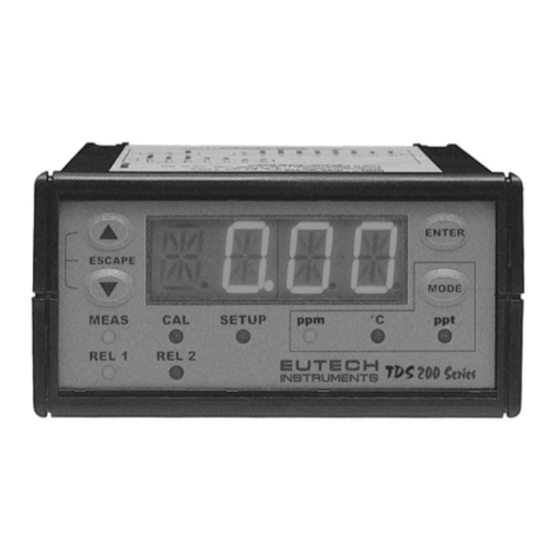
Page 7: Overview
3 OVERVIEW 3.1 Front Panel The front panel consists of a 4-digit LED display, 8 LED annunciators and 4 keys. Annunciators 1. REL 1 Displayed when Relay 1 is activated 2. REL 2 Displayed when Relay 2 is activated 3. MEAS Displayed in measurement mode 4. -
Page 8: Back Panel
3.2 Back Panel The back panel consists of three different connectors that can be used with removable terminal blocks (included): 19 18 17 16 15 14 13 12 11 10 9 8 7 6 5 4 3 2 1 1. VAC live wire 2. -
Page 9: Wiring
3.3 Wiring Caution: Ensure electrical mains is disconnected before proceeding. 1. Connect the power supply to the three-pin terminal block VAC live wire = 1 VAC neutral wire = 2 VAC protective ground wire = 3 lpha TDS 200 controller accepts voltages from 85 to 260 VAC, 50/60 Hz or DC. 2. -
Page 10: Panel-Mounting The Controller
3.4 Panel-mounting the controller The supplied mounting hardware allows surface mounting to all panels and protective enclosures. Mounting cut-out size is 91 x 45 mm. To attach the mounting to the controller: Align the catch to the side of the controller, and insert threaded rods through catch. Screw the threaded-rod through the catch in a clock-wise direction. -
Page 11: Measurement Mode
4 MEASUREMENT MODE Press MODE to toggle between: TDS measurement mode and Temperature measurement mode Total Dissolved Solids Measurement Mode The controller displays the selected TDS range number, R X (X ranges from 1 to 8), for 2 seconds before displaying the TDS measurement. TDS Range Range No., R Resolution... -
Page 12: Password
5 PASSWORD To access Calibration and Setup functions, you need to enter a password code. You cannot change calibration and setup parameters unless you first enter the password. The lpha TDS 200 controller features two separate passwords: TDS and Temperature calibration mode password = 011 Setup program password = 022 To enter the password: Press ENTER twice. - Page 13 P .000 P .000 P .0 10 P .020 P .011 P .022...
-
Page 14: Tds Calibration
6 TDS CALIBRATION IMPORTANT: When Calibration mode is entered, controller automatically goes into a “HOLD” mode where the 4-20 mA output freezes and relays are de-activated (if it was in an activated condition). Upon return to measurement mode, both 4-20mA output and relay activities resume, depending on settings. - Page 15 If any or both conditions are not satisfied, controller will display ERR 1 (blinking). Key in the password “011” using the method described in Section 5. Controller flashes the value of the standard solution. Use electrode to agitate standard solution to obtain a homogeneous solution and to dislodge any bubbles.
- Page 16 50 9 50 0 ENTER d o n e ENTER Notes: You can view the calibrated TDS value from Setup program. See Setup program P5.0. Controller displays calibrated TDS point for selected range. If calibration is not done for the selected range, controller displays ‘- - - -‘. If after thorough cleaning of electrode and ERR1 is displayed after an attempted calibration, consider changing electrode.
-
Page 17: Temperature Calibration
7 TEMPERATURE CALIBRATION IMPORTANT: When Calibration mode is entered, controller automatically goes into a “HOLD” mode where the 4-20 mA output freezes and relays are de-activated (if it was in an activated condition). Upon return to measurement mode, both 4-20mA output and relay activities resume, depending on settings. -
Page 18: Setup Mode
22 .5 25.0 ENTER d o n e 8 SETUP MODE 8.1 General Information IMPORTANT: When Setup mode is entered, controller automatically goes into a “HOLD” mode where the 4-20 mA output freezes and relays are de-activated (if it was in an activated condition). -
Page 19: Setup Mode Overview
P 1 .0 P 6 . P 2 .0 P 7 .0 P 3 .0 P 6 .0 P 4 .0 P 5 .0 8.2 Setup mode overview P1.0: Set Point 1 P1.1: select relay 1 set point value P1.2: select relay 1 as low or high set point P1.3: set relay 1 hysteresis value P2.0: Set Point 2 P2.1: select relay 2 set point value... - Page 20 P6.0: Electrode Properties P6.1: view cell correcting factor constant value after calibration P6.2: view temperature offset value after calibration (only if in ATC mode) P7.0: TDS Factor P7.1: select TDS factor for appropriate application P8.0: Reset P8.1: select yes/no to reset controller to factory defaults...
-
Page 21: Set Point 1 - P1.0
8.3 Set Point 1 – P1.0 Setup program P1.0 allows you to set parameters for relay 1. P1.1: select relay 1 set point value P1.2: select relay 1 as low or high set point P1.3: set relay 1 hysteresis value (dead band) P 1 .0 P 1 .1 P 1 .2... - Page 22 P1.2: Set relay as high or low set point Select low set point to activate Relay when measured value undershoots Set point; select high set point to activate Relay when measured value overshoots Set point. Using both SP1 and SP2, you can select lo/lo, lo/hi, hi/lo or hi/hi set points. Key in password “022”...
- Page 23 P1.3: Set Hysteresis value Hysteresis prevents rapid contact switching if measured value is fluctuating near the set point. Once activated, relay will not de-activate until measured value reaches set point plus hysteresis value. Example: Low set point is 200.0 ppm and hysteresis 100.0 ppm, relay will activate when value is below 200.0 ppm, but will not de-activate till measured TDS value rises above 300.0 ppm.
-
Page 24: Set Point 2 - P2.0
8.4 Set Point 2 – P2.0 Setup program P2.0 allows you to set parameters for relay 2. P2.1: select relay 2 set point value P2.2: select relay 2 as low or high set point P2.3: set relay 2 hysteresis value (dead band) P 2 .0 P 2 .1 P 2 .2... - Page 25 P2.2: Set relay as high or low set point Select low set point to activate Relay when measured value undershoots Set point; select high set point to activate Relay when measured value overshoots Set point. Using both SP1 and SP2, you can select lo/lo, lo/hi, hi/lo or hi/hi set points. Key in password “022”...
-
Page 26: Measurement Range Selection - P3.0
8.5 Measurement Range Selection – P3.0 Setup program P3.0 is for selecting the range of measurement. P3.1: select measurement range and corresponding cell constant P 3 .0 P 3 .1 1000 R N GE K 10 . Press ▲and ▼keys together (ESCAPE) at anytime, to leave the Setup mode and return to Measurement mode. -
Page 27: Configure Temperature Settings - P4.0
8.6 Configure Temperature Settings – P4.0 Setup program P4.0 is for selecting ATC or MTC, set temperature coefficient values, and select normalization temperature P4.1: ATC or MTC mode (default : ATC mode) P4.2: set temperature coefficient (default : 2.10 %) P4.3: set Normalization temperature (default : 25.0 P 4 .0 P 4 .1... -
Page 28: Viewing Tds Calibration Data - P5.0
8.7 Viewing TDS Calibration Data – P5.0 Program 5 is a “view only” option, which displays the value at which calibration was performed. P5.1: view Calibrated TDS value (if no calibration performed for this range, controller displays ‘- - - - ‘. These parameters will change each time you recalibrate the controller. -
Page 29: Viewing Tds / Temperature Electrode Data - P6.0
8.8 Viewing TDS / Temperature Electrode Data – P6.0 Program 6 has two “view only” options that let you check the electrode parameters for diagnostic purposes. P6.1: view revised cell correcting factor value of electrode P6.2: view temperature probe offset (ATC on only) These parameters will change each time you recalibrate the controller. -
Page 30: Set Tds Factor - P7.0
8.9 Set TDS Factor – P7.0 The alpha TDS 200 Controller allows the TDS factor to be selected, depending on the application. P .0 P7.1: Viewing Temperature electrode data Key in the password “022” as per procedure in Section 5. Press ▲key until screen displays P7.0 and TDS. - Page 31 Press ▲and ▼keys together (ESCAPE) at anytime, to leave the Setup mode and return to Measurement mode. P8.0: Controller reset Key in the password “022” as per procedure in Section 5. Press ▲key until screen displays P8.0 and RST. Press ENTER. Screen will scroll P8.1, then ‘No’.
-
Page 32: Relays
9 RELAYS The alpha TDS 200 features two SPDT non-powered relays; rated for 6A at 110 VAC, 250 VAC maximum. When your process exceeds the set parameters of a relay set point, the REL 1 or REL 2 indicator lights up. To set parameters for relay one and relay two, see Setup programs P1.0 and P2.0. -
Page 33: Specifications
11 SPECIFICATIONS TDS Range Resolution Cell Constant 0.00 – 10.00 ppm 0.01 ppm 0.0 – 100.0 ppm 0.1 ppm 0.0 – 100.0 ppm 0.1 ppm 0 – 1000 ppm 1 ppm 0.00 – 5.00 ppt 0.01 ppt 0.00 – 10.00 ppt 0.01 ppt 0.0 –... -
Page 34: Accessories
12 ACCESSORIES Product Description Code no. TDS cell, Epoxy body, Graphite sensor, w/3-wire Pt100, k = 0.1 ECCONSEN89X TDS cell, Epoxy body, Graphite sensor, w/3-wire Pt100, k = 1.0 ECCONSEN88X Note: Above TDS electrodes withstand up to 3 bar pressure. These cells have integral 1.0 m, 5-wire double-shielded open-ended cable. - Page 35 Appendix 1: Simple Explanation on the Function of Hysteresis S P 1 S e t t o L O S P 2 S e t t o H I R E L A Y O N The controller relay activates when the set-point is reached.
- Page 36 Appendix 3: External Relays The relays on the alpha TDS 200 series controller are rated for 6 amps at 110 VAC and can be wired directly to your final control element (provided its power requirements does not exceed this). However, to preserve the life of your controller, or if higher power is needed, it is recommended that you use the controller relay to drive an external relay.
-
Page 37: General Information
When applying for authorisation, please include data requiring the reason of return. Items must be carefully packed to prevent damage in shipment and insured against possible damage or loss. Eutech Instruments will not be responsible for any damage resulting from careless or insufficient packing. - Page 38 NOTES...
- Page 40 For more information on Eutech Instruments products, contact your nearest Eutech Instruments distributor or visit our website listed below: Manufactured by: Distributed by: Eutech Instruments Pte Ltd. Blk 55, Ayer Rajah Crescent, #04-16/24 Singapore 139949 Tel: (65) 6778 6876 Fax: (65) 6773 0863 E-mail: marketing@eutechinst.com...
Need help?
Do you have a question about the ALPHA TDS 200 TOTAL DISSOLVED SOLIDS CONTROLLERTRANSMITTER and is the answer not in the manual?
Questions and answers