
Related Manuals for EUTECH INSTRUMENTS ALPHA PH 200 PHORP CONTROLLERTRANSMITTER


Summary of Contents for EUTECH INSTRUMENTS ALPHA PH 200 PHORP CONTROLLERTRANSMITTER
- Page 1 Instruction Manual α lpha pH 200 1/8 DIN pH / ORP Controller with Temperature display and Transmitter Technology Made Easy ... 68X276101 Rev 3 1/2004...
- Page 3 200 controller/transmitter, do not hesitate to contact the nearest Eutech Instruments Authorized Distributor. Eutech Instruments cannot accept any responsibility for damage or malfunction to the controller/transmitter caused by improper use of the instrument. Remember to fill in the guarantee card and mail it mail to your Authorized Distributor or Eutech Instruments Pte Ltd.
-
Page 4: Table Of Contents
TABLE OF CONTENTS INTRODUCTION ................... 1 SAFETY INFORMATION ................2 OVERVIEW....................3 ................3 RONT ANEL ................4 ANEL ..................5 IRING ........6 ANEL MOUNTING THE CONTROLLER MEASUREMENT MODE................7 PASSWORD....................8 PH CALIBRATION ..................10 ORP CALIBRATION ................... 13 TEMPERATURE CALIBRATION.............. -
Page 5: Introduction
1 INTRODUCTION Thank you for purchasing a pH 200 ⅛ DIN pH/ORP Controller. This controller is part of a series of quality process controllers available from Eutech Instruments. These sturdy, economical pH/ORP controllers are designed with the features and reliability of a much more expensive instrument. -
Page 6: Safety Information
2 SAFETY INFORMATION The Eutech Controller/Transmitter shall be installed and operated only in the manner specified in the Instruction manual. Only skilled, trained or authorized person should carry out installation, setup and operation of the instrument. Before powering up the unit, make sure that power source it is connected to, is as specified in the top label. -
Page 7: Overview
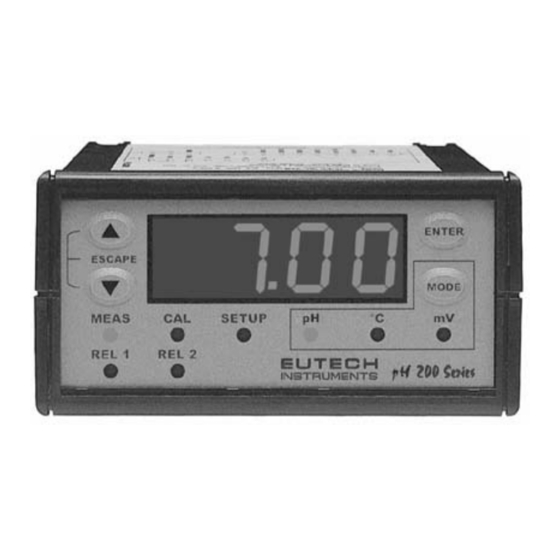
3 OVERVIEW 3.1 Front Panel The front panel consists of a 4-digit LED display, 8 LED annunciators and 4 keys. Annunciators 1. REL 1 Displayed when Relay 1 is activated 2. REL 2 Displayed when Relay 2 is activated 3. MEAS Displayed in measurement mode 4. -
Page 8: Back Panel
3.2 Back Panel The back panel consists of four different connectors that can be used with removable terminal blocks (included): pH/ORP WARNING A. 3 pin connector (for power supply) B. 9 pin connector (for relays) C. 7 pin connector (for temperature sensor) D. -
Page 9: Wiring
3.3 Wiring Caution: Ensure electrical mains is disconnected before proceeding. 1. Connect the power supply to the three-pin terminal block (D) • VAC protective ground wire = 3 • VAC neutral wire = 2 • VAC live wire = 1 The alpha pH 200 controller accepts voltages from 85 to 260 VAC, 50/60 Hz or 2. -
Page 10: Panel-Mounting The Controller
3.4 Panel-mounting the controller The supplied mounting hardware allows surface mounting to all panels and protective enclosures. Mounting cut-out size is 91 x 45 mm. To attach the mounting to the controller: Align the catch to the side of the controller, and insert threaded rods through catch. -
Page 11: Measurement Mode
4 MEASUREMENT MODE Press MODE to toggle between: • pH (or ORP) measurement mode • Temperature measurement mode pH (ORP) measurement mode The controller starts up in the mode when last powered off (pH or ORP). The appropriate annunciator lights up. NOTE: Select pH or ORP measurement mode in Setup program P3.1. -
Page 12: Password
5 PASSWORD To access Calibration and Setup functions, you need to enter a password code. You cannot change calibration and setup parameters unless you first enter the password. The alpha pH 200 controller features two separate passwords: • pH (ORP) calibration mode password = 011 •... - Page 13 P . 000 P . 000 P .0 1 0 P .020 P . 0 11 P . 022 P . 0 11 P . 022 - 9 -...
-
Page 14: Ph Calibration
6 PH CALIBRATION The alpha pH 200 controller features seven preset buffer values (pH 1.68, 4.01, 6.86, 7.00, 9.18, 10.01, 12.45) for quick auto-calibration at one or two points. The first calibration point must be pH 6.86 or 7.00. When you calibrate this instrument, you need to use FRESH standard pH buffer solution that matches these values. - Page 15 7 .0 0 bU f f ENTER 6.9 7 ENTER 7 .0 0 d o n e ENTER 1 0 .0 1 bU f f ENTER 1 0.0 3 ENTER 10.0 1 d o n e ENTER - 11 -...
- Page 16 If you are performing 1-point calibration, press ▲/▼keys together to return to measurement mode. If you are performing two-point calibration, proceed with the next step. Use ▲/▼keys to select the next buffer value (pH 1.68, 4.01, 9.18, 10.01 and 12.45). Make sure the electrode is in the correct buffer solution.
-
Page 17: Orp Calibration
7 ORP CALIBRATION mV (ORP) values may be offset at up to ±150 mV to agree with a calibration solution or an established work standard. Key in the password “011” as per procedure described in Section 5. Controller will blink with uncalibrated mV output of your electrode. Determine the mV value of your solution with an accurate meter (such as the pH 6). -
Page 18: Temperature Calibration
8 TEMPERATURE CALIBRATION This controller features selectable Automatic Temperature Compensation (ATC) or Manual Temperature Compensation (MTC). ATC: ATC mode requires a Pt 100 temperature element. ATC automatically compensates for temperature fluctuations. You can offset your ATC temperature reading by ±10 Important: If there is no temperature element wired to the controller and ATC is selected on, the screen will flash in pH or ORP mode, and you will see an error message (OR) in temperature mode. -
Page 19: Setup Mode
9 SETUP MODE 9.1 General Information IMPORTANT: When Setup mode is entered, the controller automatically goes into a “HOLD” mode where the 4-20 mA output freezes and the relays are de-activated (if it was in an activated condition). Upon return to the measurement mode, both the 4-20mA output and relay activities resume, depending on the settings. -
Page 20: Setup Mode Overview
9.2 Setup mode overview P1.0: Set Point 1 P1.1: select relay 1 set point value P1.2: select relay 1 as low or high set point P1.3: set relay 1 hysteresis value P2.0: Set Point 2 P2.1: select relay 2 set point value P2.2: select relay 2 as low or high set point P2.3: set relay 2 hysteresis value P3.0: Configuration... -
Page 21: Set Point 1 - P1.0
9.3 Set Point 1 – P1.0 Setup program P1.0 allows you to set parameters for relay 1. P1.1: select relay 1 set point value P1.2: select relay 1 as low or high set point P1.3: set relay 1 hysteresis value (dead band) P 1 .0 P 1 .1 P 1 .2... - Page 22 P1.3: Set Hysteresis value Hysteresis prevents rapid contact switching if your value is fluctuating near the set point. Once activated, the relay will not return to resting position until the measured value has passed through the set point plus hysteresis value. Example: With a low set point of 4.00 and a hysteresis value of 0.5, the relay will activate at pH values below 4.00, but will not de-activate till the measured pH value rises above pH 4.50.
-
Page 23: Set Point 2 - P2.0
9.4 Set Point 2 – P2.0 Setup program P2.0 allows you to set parameters for relay 2. P2.1: select relay 2 set point value P2.2: select relay 2 as low or high set point P2.3: set relay 2 hysteresis value (dead band) P 2 .0 P 2 .1 P 2 .2... - Page 24 P2.3: Set Hysteresis value Hysteresis prevents rapid contact switching if your value is fluctuating near the set point. Once activated, the relay will not return to resting position until the measured value has passed through the set point plus hysteresis value. Example: With a high set point of 10.00 and a hysteresis value of 0.5, the relay will activate at pH values above 10.00, but will not de-activate till the measured pH value decreases below pH 9.50.
-
Page 25: Configuration - P3.0
9.5 Configuration – P3.0 Setup program P3.0 let you configure controller parameters. P3.1: select pH or ORP mode of operation P3.2: select symmetrical or asymmetrical input mode P3.3: select temperature compensation (manual or automatic) P 3. 0 P 3. 1 P 3 .2 P 3 . - Page 26 P3.3: Select temperature compensation This controller features selectable automatic temperature compensation (ATC) or manual temperature compensation (MTC). ATC automatically compensates for temperature fluctuations; MTC let you select a specific value at which temperature will be compensated. ATC readings require a temperature sensor. Key in the password “022”...
-
Page 27: Viewing Calibration Points: Ph Or Orp - P4.0
9.6 Viewing Calibration points: pH or ORP – P4.0 Setup program P4.0 lets you view the current points at which the controller is calibrated. This is a “view only” parameter. P4.1: first calibration point P4.2: second calibration point (pH only) When controller has no calibration points in memory, the display will show “-------“. -
Page 28: Viewing Ph Electrode Data - P5.0
9.7 Viewing pH Electrode Data – P5.0 In pH mode, Program 5 has three “view only” options that lets you check the electrode parameters for diagnostic purposes. P5.1: view pH electrode offset P5.2: view pH electrode slope P5.3: view temperature probe offset (ATC on only) These parameters will change each time you recalibrate the controller. -
Page 29: Viewing Orp Electrode Data - P5.0
9.8 Viewing ORP Electrode Data – P5.0 In ORP mode, Program 5 has two “view only” options that lets you check the electrode parameters for diagnostic purposes. P5.1: view ORP electrode offset P5.2: view temperature probe offset (ATC on only) These parameters will change each time you recalibrate the controller. -
Page 30: Controller Reset - P6.0
9.9 Controller Reset – P6.0 This parameter lets you reset the controller. All pH and ORP calibration data will be cleared, and all Setup parameters revert to factory default values. Temperature mode (ATC or MTC) and calibration data remains unchanged. P 6 .0 P 6 .1 y e S... -
Page 31: Relays
10 RELAYS The alpha pH 200 features two SPDT non-powered relays; rated for 6A at 110 VAC, 250 VAC maximum. When your process exceeds the set parameters of a relay set point, the REL 1 or REL 2 indicator lights up. To set parameters for relay one and relay two, see Setup programs P1.0 and P2.0. -
Page 32: Specifications
13 SPECIFICATIONS pH Range 0.00 to 14.00 pH Resolution/Accuracy 0.01 / ± 0.01 pH mV Range -999 to 1000 mV Resolution/Accuracy 1 / ± 2 mV Temperature -10 to 110 Resolution/Accuracy 0.1 / ± 0.5 Sensor Pt 100 (3-wire) Temperature Compensation Automatic / Manual (0 to 100 °C) Set-point And Controller Functions Function... -
Page 33: Accessories
14 ACCESSORIES Product Description Code no. pH Combination Electrode with Pt 100 RTD and PMP EC-100GTSO-05B pH Combination Electrode with HF resistant glass (w/o EC-ARTSOHF-05B ATC & PMP) pH Combination Electrode with PMP (w/o ATC) EC-ARGTSO-05B pH Combination Electrode with high temperature (110 EC-ARHTTSO-05B and high pressure resistance (9 bar) (w/o ATC &... - Page 34 Appendix 1: Asymmetrical / Symmetrical Mode The alpha pH 200 controller can be operated in the asymmetrical or symmetrical modes (See Set up Program P3.2). Asymmetrical mode: Asymmetrical mode works well in environments where there is little or no electrical noise. When there is noise, the noise acts as a common signal, which is picked up by both the pH and the reference electrodes.
- Page 35 Symmetrical mode: For noisy electrical environments, the alpha pH 200 controller offers Symmetrical Mode operation. To take advantage of Symmetrical operation, you must have an electrode with a solution ground (potential matching) pin, such as the EC-ARGTSO-05B or EC- 100GTSO-05B. If your electrode does not have a solution ground, be sure to set the controller to Asymmetrical mode.
- Page 36 Appendix 2: Simple Explanation on the Function of Hysteresis SP1 Set to LO SP2 Set to HI RELAY ON The controller relay activates when the set-point is reached. In the reverse direction, it does not de- activate when the value reaches the set-point.
- Page 37 Appendix 4: External Relays The relays on the alpha pH 200 series controller are rated for 6 amps at 110 VAC and can be wired directly to your final control element (provided its power requirements does not exceed this). However, to preserve the life of your controller, or if higher power is needed, it is recommended that you use the controller relay to drive an external relay.
-
Page 38: General Information
15 GENERAL INFORMATION Warranty Eutech Instruments warrants this product to be free from significant deviations in material and workmanship for a period of one year from the date of purchase. If repair is necessary and has not been the result of abuse or misuse within the warranty period, please return by freight pre-paid and amendment will be made without any charge. - Page 40 For more information on Eutech Instruments products, contact your nearest Eutech Instruments distributor or visit our website listed below: Manufactured by: Distributed by: Eutech Instruments Pte Ltd. Blk 55, Ayer Rajah Crescent, #04-16/24 Singapore 139949 Tel: (65) 6778 6876 Fax: (65) 6773 0836 E-mail: marketing@eutechinst.com...
Need help?
Do you have a question about the ALPHA PH 200 PHORP CONTROLLERTRANSMITTER and is the answer not in the manual?
Questions and answers