
Related Manuals for EUTECH INSTRUMENTS ALPHA RES 1000 RESISTIVITY CONTROLLERTRANSMITTER


Summary of Contents for EUTECH INSTRUMENTS ALPHA RES 1000 RESISTIVITY CONTROLLERTRANSMITTER
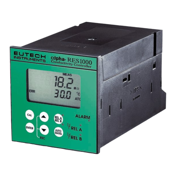
- Page 1 Instruction Manual αlpha-RES1000 Resistivity Controller/Transmitter Technology Made Easy ... 68X216807 rev 3 12/04...
- Page 4 The information presented in this manual is subject to change without notice as improvements are made, and does not represent a commitment on part of Eutech Instruments Pte Ltd. Eutech Instruments cannot accept any responsibility for damage or malfunction of the unit due to improper use of the instrument.
-
Page 5: Table Of Contents
αlpha-RES1000 Operating Instructions TABLE OF CONTENTS INTRODUCTION ....................1 ..................1 ESCRIPTION OF ....................1 PPLICATIONS ASSEMBLY AND INSTALLATION..............2 ............2 EASUREMENT AND ONTROL YSTEM ..................2 IMENSIONS ELECTRICAL CONNECTION................3 ...................3 ONNECTION IAGRAM ....................4 ANEL OVERVIEW ......................5 ..................5 EYPAD AND ISPLAY 4.1.1 Keypad ......................5 4.1.2 Display ....................... - Page 6 αlpha-RES1000 Operating Instructions 7.4.5 Maximum Pulse Length (tPL) or Maximum Frequency (FPF) ......17 ............17 EASUREMENT ANGE SUB FUNCTION 7.5.1 Entering the Measuring Range sub-function ........... 17 7.5.2 Selecting Measuring Range sub-function............17 7.5.3 Measurement Range available in the Controller ..........18 7.5.4 Current Output (rng) sub-function..............
-
Page 7: Introduction
αlpha-RES1000 Operating Instructions Introduction Description of Unit Thank you for purchasing Eutech’s ¼ DIN alpha-1000 series Resistivity process controllers. This unit is used for measuring the Resistivity of a solution in mega-ohms. You can use this unit to measure Resistivity with limit control. This controller has many user-friendly and safety features which include: •... -
Page 8: Assembly And Installation
αlpha-RES1000 Operating Instructions Assembly and Installation Measurement and Control System A typical measurement system consists of: • a αlpha-RES1000 process controller • a suitable Resistivity electrode with the appropriate Cell constant and integrated temperature sensor Pt 1000 or Pt 100, •... -
Page 9: Electrical Connection
αlpha-RES1000 Operating Instructions Electrical Connection Connection Diagram 1 9 2 0 2 1 22 PE/S Pt 1000/100 Signal Input Resistivity R e l a y A Hold Input S ignal O u t p u t P o w e r M a i n s Relay B A larm PE/S... -
Page 10: Back Panel
αlpha-RES1000 Operating Instructions Back Panel The back panel consists of two connectors. The first connector is the 17-way PCB edge connector and the other is the 5-way connector. Connection for the 17-way screw terminals (from left to right): 1. AC mains live wire 10. -
Page 11: Overview
αlpha-RES1000 Operating Instructions Overview 4.1 Keypad and Display 4.1.1 Keypad • Perform rapid calibration • Allows entry to Set up mode • Select individual functions within the function group of Set up mode • Store input data in the Set up mode •... -
Page 12: Function Groups
αlpha-RES1000 Operating Instructions Function Groups The main function and sub-function groups are organised in a matrix format for configuration and selection of parameters. The main function groups are: Temperature Coefficient settings (tC) Temperature Measurement / compensation settings (SEt Control relay 1 configuration (SP1) Control relay 2 configuration (SP2) Control type (Cntr) Current output (rng) -
Page 13: Control Concept
αlpha-RES1000 Operating Instructions Control Concept The main function and sub-function groups are organised in a matrix format as shown below. These functions can be accessed via the front keypad for configuration and selection of parameters. Controller offers three levels of password protection: (1) for viewing all SETUP Configuration without the facility to make changes;... -
Page 14: Measurement
αlpha-RES1000 Operating Instructions Measurement Display in Measurement mode When controller is powered on, it automatically enters into the Measurement mode after large dual LCD briefly displays all segments. The upper display shows the measured Resistivity value, while lower display shows temperature value. Annunciators at right side of the display indicate mΩ... -
Page 15: How To Enter And Change Parameters In Advanced Setup Mode
αlpha-RES1000 Operating Instructions NOTE: To view (not change) electrode condition, push ENTER key when the security code reads “000”. 5.2.1.1 Clearing Calibration security code from display The calibration security code automatically resets from “11” to “000” after returning to Measurement mode. -
Page 16: Calibration Mode
αlpha-RES1000 Operating Instructions Calibration Mode Calibration mode can be accessed directly from Measurement mode by pressing CAL key and entering the Calibration security code; or from the Advanced Setup mode. Resistivity Calibration Calibration is always carried out in the specific range selected. The Resistivity Controller allows a one- point calibration. -
Page 17: Advanced Set-Up Mode
αlpha-RES1000 Operating Instructions Advanced Set-Up Mode Temperature Coefficient sub-function This sub-function allows you to select correct temperature coefficient for optimum operations. For applications in pure water or ultra-pure water industries, select “Pur” temperature coefficient option. For all other applications, select “Lin” temperature coefficient. Controller allows further input of temperature coefficient values, independently for process and for calibrating solutions. -
Page 18: Temperature Calibration (Atc Mode Only)
αlpha-RES1000 Operating Instructions Temperature calibration (ATC mode only) Enter Advanced Set-up mode. Push the ENTER key and scroll to HOLD SETUP Advanced Set-up security code “22”. Push the ENTER key again. Press the ∆ or ∇ keys to scroll through the sub-menus until the display shows “Set C”. -
Page 19: Control Relay A/Control Relay B (Sp1/Sp2) Sub-Function
αlpha-RES1000 Operating Instructions Continue with additional Advanced Set-up procedures, or return to Measurement mode by pressing ∆ and ∇ keys (escape) simultaneously. Control Relay A/Control Relay B (SP1/SP2) sub-function SP1 option sets operating parameters for Relay A; and SP2 for relay B. Since these groups have the same set-up parameters, they are described together. -
Page 20: Selecting A Hysteresis (Dead Band) Value
αlpha-RES1000 Operating Instructions Proceed to 7.3.4, or return Measurement mode by pressing ∆ and ∇ keys simultaneously (escape). 7.3.4 Selecting a hysteresis (dead band) value (0.000 to 0.200 mΩ or 0.00 to 2.00 mΩ) Hysteresis prevents rapid contact switching if the value is fluctuating near the set point. It does this by overshooting the set point value to a specified hysteresis value (default is 0.20 mΩ). -
Page 21: Setting An Off-Delay Time Lag
αlpha-RES1000 Operating Instructions 7.3.6 Setting an off-delay time lag You can set as time delay for each relay, which stops the relay from switching off the moment the value reached the set point and hysteresis. This controller lets you set a 0 to 1999 seconds time delay before your relay deactivates. -
Page 22: Choosing Break/Make Contact Relay Type
αlpha-RES1000 Operating Instructions 1) Follow directions in 7.4.1 to enter Controller mode. 2) Press the ENTER key. The upper display shows the current controller type and the lower display shows “tYP”. 3) Press the ∆ and ∇ keys to select your controller type. L.Ct = limit value pickup (on/off control). -
Page 23: Maximum Pulse Length (Tpl) Or Maximum Frequency (Fpf)
αlpha-RES1000 Operating Instructions 7.4.5 Maximum Pulse Length (tPL) or Maximum Frequency (FPF) Note: If the controller type “oFF” or “L.Ct” is set, the parameters listed in 7.4.4 and 7.4.5 are blanked out. This mode lets you set the maximum pulse length or the maximum frequency at which the relay will operate. -
Page 24: Measurement Range Available In The Controller
αlpha-RES1000 Operating Instructions 7.5.3 Measurement Range available in the Controller Range No. Range Resolution Default cell K 0.01 0.000 – 19.99 mΩ 0.01 mΩ 0.00 – 1.999 mΩ 0.001 mΩ 7.5.4 Current Output (rng) sub-function This sub-function lets you set the transmitter current output range of this unit. The difference between the upper and lower range has to be a minimum of 20% of Full Scale, anywhere on the scale. -
Page 25: Selecting Resistivity Value At 20Ma
αlpha-RES1000 Operating Instructions 7.5.7 Selecting Resistivity value at 20mA This parameter selects the resistivity value at which transmitter output will be 20mA. Follow directions in 7.5.4 to enter Current Output mode. Press the ENTER key until upper display shows a resistivity value and lower display shows “r.20”. Press the ∆... -
Page 26: Selecting The Alarm Time Lag (If The Relay 3 Is Set To Alarm)
αlpha-RES1000 Operating Instructions 7.6.3 Selecting the alarm time lag (if the relay 3 is set to Alarm) This parameter group lets you select a period of time before the alarm activates when your set point has been overshot. You can select from 0 to 1999 seconds. Follow directions in 7.6.1 to enter Configuration mode. -
Page 27: Input Line Resistance Adjust
αlpha-RES1000 Operating Instructions 7.6.6 Input Line Resistance Adjust This function compensates for the line resistance of the cable to its cell. Follow directions in 7.6.1 to enter Configuration mode. HOLD SETUP Press ENTER key until upper display shows “0.0” and lower display shows “L.Ad”. -
Page 28: Auto/Manual Mode
αlpha-RES1000 Operating Instructions Auto/Manual Mode Regardless of mode, control devices connected to Relay A or Relay B can be operated from front panel of controller. In Automatic mode, controller’s set point values activate relays. In Manual mode, manual control of relays is possible to prime the pump or check pump status. Auto mode (mode after switch-on) To view set-point values: Press RELAY SELECTION (Rel A/Rel B) key. -
Page 29: Technical Specifications
αlpha-RES1000 Operating Instructions Technical Specifications Resistivity Range Resolution Default Cell Constant, K 0.01 0.00 to 19.99 mΩ/cm 0.01 mΩ/cm 0.000 to 1.999 mΩ/cm 0.001 mΩ/cm Temperature -9.9 to 125 Resolution Relative Accuracy ± 0.5 Sensor Pt 1000/Pt 100 Temperature Compensation Auto / manual (reference at 25.0 Set-point and Controller Functions Controller characteristics... -
Page 30: 10 General Information
10.1 Warranty Eutech Instruments warrants this product to be free from significant deviations in material and workmanship for a period of one year from the date of purchase. If repair is necessary and has not been the result of abuse or misuse within the warranty period, please return by freight pre-paid and amendment will be made without any charge. -
Page 31: 11 Appendices
αlpha-RES1000 Operating Instructions 11 Appendices Appendix 1 – Jumper Positions Jumper Positions - Internal to the controller JP 1 Selects the input voltage 220 VAC. JP 2 Selects the input voltage 110 VAC. JP 6 Selects the temperature sensor for Pt1000/Pt100 Fuse Note that there is a fuse (slow-blow 100mA) internal to the controller. -
Page 32: Conductivity
αlpha-RES1000 Operating Instructions Appendix 2 – Conductivity / Resistivity of Various Aqueous Solutions at 25 Conductivity Resistivity Pure Water 0.05 uS/cm MΩ-cm Power Plant Boiler Water 0.05 - 1 uS/cm 1 - 18 MΩ-cm Distilled Water uS/cm MΩ-cm De-ionized Water 0.1 - 10 uS/cm 0.1 - 10... -
Page 33: Appendix 4 - Pure Water Curve
αlpha-RES1000 Operating Instructions Appendix 4 – Pure Water Curve Resistivity of Pure Water 95 100 Temp °C... - Page 36 For more information on Eutech Instruments products, contact your nearest Eutech Instruments distributor or visit our website listed below: DISTRIBUTED BY: Manufactured by: Eutech Instruments Pte Ltd. Blk 55 Ayer Rajah Crescent #04-16/24 Singapore 139949 Tel: (65) 6778 6876 Fax: (65) 6773 0836 E-mail: marketing@eutechinst.com...
Need help?
Do you have a question about the ALPHA RES 1000 RESISTIVITY CONTROLLERTRANSMITTER and is the answer not in the manual?
Questions and answers