
Related Manuals for EUTECH INSTRUMENTS ALPHA PH 800 PHORP CONTROLLERTRANSMITTER


Summary of Contents for EUTECH INSTRUMENTS ALPHA PH 800 PHORP CONTROLLERTRANSMITTER
-
Page 1: Operating Instructions
EUTECH INSTRUMENTS lpha-pH800 pH and ORP Controller/Transmitter Operating Instructions 68X216813 03/99... - Page 2 If you have doubts in the use of the instrument, please do not hesitate to contact the nearest Eutech Instruments’ Authorised Distributor. The information presented in this manual is subject to change without notice as improvements are made, and does not represent a commitment on part of Eutech Instruments Pte Ltd.
-
Page 3: Table Of Contents
TABLE OF CONTENTS 1 INTRODUCTION....................1 Description of Unit..................1 Applications....................2 ASSEMBLY AND INSTALLATIONS ............. 3 Measurement and Control System............3 Unit Dimensions ..................3 ELECTRICAL CONNECTIONS............... 4 Connection Diagram................4 Back Panel....................6 OVERVIEW....................... 8 Keypad and Display................. 8 Function Groups.................... -
Page 5: Introduction
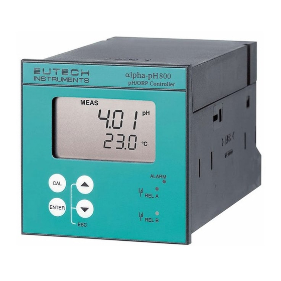
INTRODUCTION 1.1 Description of Unit Thank you for purchasing Eutech’s ¼ DIN alpha-800 series pH/ORP process controllers. This unit is used for measuring either pH or ORP parameter one at a time, and the operational mode is switchable from the menu. -
Page 6: Applications
Applications Use this controller in panel mounted enclosures for applications such as water treatment and monitoring, galvanic-decontamination, chemical processing food processing, clean or waste water control and neutralisation process... -
Page 7: Assembly And Installations
ASSEMBLY AND INSTALLATIONS 2.1 Measurement and Control System A typical measurement system consists of: a pH/ORP process controller a pH/ORP combination electrode with integrated or separate temperature sensor Pt 100/1000, an immersion, flow or process assembly with or without a potential matching pin (PMP) a final control element such as pump or valve a recorder... -
Page 8: Electrical Connections
ELECTRICAL CONNECTIONS 3.1 Connection Diagram 19 20 21 22 PE/S Potential Matching Pin (PMP) Pt 100 Signal Input pH/ORP Relay A Hold Input Signal Output Power Mains Relay B PE/S * ) indicated contact positions are for currentless conditions... - Page 9 Temp. PE N 0 / PA Symmetrical high-impedance connections Measuring Cable Potential pH Combination Matching Pin (PM) Electrode Temp. PE N 0 / PA Asymmetrical connections Measuring Cable Potential pH Combination Matching Pin (PM) Electrode...
-
Page 10: Back Panel
3.2 Back Panel The back panel consists of two connectors. The first connector is the 17-way PCB edge connector and the other is the 5-way connector. Connection for the 17-way screw terminals (from left to right): 1.AC mains live wire 10.No connection 2.AC mains neutral wire 11.No connection... - Page 11 Pt100/ PAL S/ Pt1000 FUSE 250VAC 100mA (F) RELAY A RELAY B HOLD...
-
Page 12: Overview
OVERVIEW 4.1 Keypad and Display 4.1.1 Keypad Perform rapid 2-point calibration and view electrode status Allows entry to Set up mode Select individual functions within the function group of Set up mode Store input data in the Set up mode Start calibration in the calibration mode Select various function groups in the Set up mode. -
Page 13: Function Groups
Function Groups The main function and sub-function groups are organised in a matrix format for configuration and selection of parameters. The main function groups are: 1) Offset adjustment (OFS) 2) Temperature Measurement / compensation settings (Set 3) Control relay 1 configuration (SP1) 4) Control relay 2 configuration (SP2) 5) Configuration (ConF) 6) Calibration (CAL pH) -
Page 14: Measurement
MEASUREMENT 5.1 Display in Measurement mode When the controller is initially powered on, it automatically enters into the Measurement mode after the large dual LCD displays all segments briefly. The upper display shows the measured pH or ORP value, while the lower display shows either the temperature value if the controller is set for pH measurement or “OrP”... -
Page 15: Calibration
CALIBRATION Direct Calibration from the Measurement mode is possible via the CAL key. The Calibration procedure can also be accessed from the Advanced Setup mode. 6.1 pH Calibration This unit features five preset buffer values (1.00, 4.00, 6.86 or 7.00, 9.00, 9.18 and 10.00) for quick, two-point auto calibration. - Page 16 symmetrical mode, immerse the potential matching pin in the buffer. 4) Press the ENTER key to start the calibration at pH 7 (or pH 6.86). The electrode indicator and CAL indicator both flash. The controller automatically adjusts the reading to match the buffer value. 5) The lower display will now show its next lower ‘pH’...
-
Page 17: Orp - Mv Calibration
6.2 ORP – mV Calibration This mode allows one-point calibration. 1) Enter Calibration mode. While in Measurement SETUP mode, push the CAL key. Press the ENTER key. The upper and lower display reads “CAL OrP”. HOLD Note: If the upper and lower display read “CAL PH”, see section 7.4 for procedures on how to switch from pH to ORP mV readings. -
Page 18: Advanced Set Up Mode
ADVANCED SET UP MODE 7.1 Electrode Offset (OFS) sub-function This option is available only in the pH mode. An allowance of 120mV is allowed to correct for electrode deviations. This feature is useful for prolonged on-line applications. The controller will add or subtract the value from the measured pH and display the correct value. -
Page 19: Setting Temperature
7.2 Setting temperature (Set C) sub-function 7.2.1 Selecting automatic or manual temperature compensation 1) Enter Advanced Set-up mode by pressing the ENTER key. 2) Press the keys to scroll until the SETUP display shows “Set C”. HOLD o o o o C C C C 3) Press the ENTER key. - Page 20 4) Press the keys to scroll the lower display to match the correct value. The upper display will now show the offset value. You can offset temperature up to 5) Press the ENTER key to confirm your selection. 6) Continue with additional Advanced Set-up procedures, or return to the Measurement mode by pressing the keys (escape) simultaneously.
- Page 21 5) Press the keys to adjust the calibration temperature value, between –9.9 and 125 6) Press the ENTER key to confirm. 7) Continue with additional Advanced Set-up procedures, or return to Measurement mode by pressing the keys (escape) simultaneously.
-
Page 22: Control Relay A/Control Relay B (Sp1/Sp2) Sub-Function
7.3 Control Relay A/Control Relay B (SP1/SP2) sub- function The SP1 option sets the operating parameters for Relay A; the SP2 option sets the operating parameters for relay B. Since these groups have the same set-up parameters, they are described together. 7.3.1 Entering the Set point 1 (Set point 2) sub-function 1) Enter Advanced Set-up mode. - Page 23 1) Follow directions in 7.3.1 to enter Control Relay mode. 2) Press the ENTER key until the upper display shows Lo or Hi and the lower display shows SP1 (SP2). 3) Press the keys to select low (lo) or high (hi) set point for SP1 (SP2).
- Page 24 5) Proceed to 7.3.5 step 3, or return to Measurement mode by pressing keys simultaneously (escape). NOTE: Please refer to Appendix 3 for a graphical representation of the Hysteresis. 7.3.5 Setting an on-delay time lag You can set as time delay for each relay, which stops the relay from switching on the moment the set point is exceeded.
- Page 25 3) Press the keys to enter off-delay time for Set point 1 (Set point 2). The controller will delay activation for the number of seconds (0 to 2000) you select. 4) Press the ENTER key to confirm your selection. 5) Continue with Advanced Set-up mode procedures, or return to Measurement mode by pressing the keys simultaneously (escape).
-
Page 26: Configuration (Conf) Sub-Function
Configuration (ConF) sub-function The options available in this sub-function allows the controller to be configured as a pH or ORP controller. 7.4.1 Entering the Configuration sub-function 1) Enter Advanced Set-up mode. Press the ENTER key. 2) Press the keys to scroll until the upper display shows “ConF”. 7.4.2 Selecting pH or ORP mV measurement SETUP ConF... -
Page 27: Calibration (Cal) Sub-Function
7.4.3 Reverting to factory default settings Use this parameter to reset all settings to factory default. Changing from “no” to “YES” and pressing the ENTER key resets all settings to factory default. WARNING: If “Yes” is selected, all settings input SETUP will be overwritten! HOLD... -
Page 28: Technical Specifications
TECHNICAL SPECIFICATIONS pH Range -2.00 to 16.00 pH Resolution 0.01 pH Relative Accuracy 0.01 pH mV Range - 1000 to +1000 mV Resolution 1 mV Relative Accuracy 1 mV Temperature - 9.9 to + 125.0 Resolution Relative Accuracy Sensor Pt 100 /Pt 1000 (jumper selectable) Temperature Compensation Auto / manual (reference at 25.0 Set-point and Controller Functions... -
Page 29: Accessories
10 GENERAL INFORMATION 10.1 Warranty Eutech Instruments warrants this product to be free from significant deviations in material and workmanship for a period of one year from the date of purchase. If repair is necessary and has not been the result of abuse or misuse within the warranty period, please return by freight pre-paid. -
Page 30: Return Of Goods
10.3 Return of Goods Authorisation must be obtained from Eutech Instruments’ Customer Service Dept. to issue a RGA (Return of Goods Authorisation) number before returning items for any reason. When applying for authorisation, please include data requiring the reason of return. Items must be carefully packed to prevent damage in shipment and insured against possible damage or loss. -
Page 31: Appendices
11 APPENDICES 11.1 Appendix 1 Jumper Positions - Internal to the controller JP 1 Selects the input voltage 220 VAC. JP 2 Selects the input voltage 110 VAC. JP 3 Solder bridge selects between Pt100 and Pt1000. Fuse Note that there is a fuse (slow-blow 100mA) internal to the controller. - Page 32 11.2 Appendix 2 The following table shows the various pH values at different temperature of the solution during calibration. Temperature pH 1.68 pH 4.01 pH 6.86 pH 7.00 pH 9.18 pH 10.01 (tetra borate ) (carbonate) (oxalate) (phthalate) (tetraoxalate) (neutral phosphate) 1.67 4.01...
- Page 33 11.3 Appendix 3 Simple Explanation on the Function of Hysteresis SP1 Set to LO SP2 Set to HI RELAY ON RELAY OFF 10.0 FORWARD DIRECTION HYSTERESIS BAND REVERSE DIRECTION (DEFAULT = 0.5 pH) The controller relay activates when the set-point is reached. In the reverse direction, it does not de-activate when the value reaches the set-point.
- Page 34 CALIBRATION RECORD Calibration Date Electrode Slope Electrode Offset...
Need help?
Do you have a question about the ALPHA PH 800 PHORP CONTROLLERTRANSMITTER and is the answer not in the manual?
Questions and answers