Table of Contents
Advertisement
Quick Links
Installation Guide
Power Monitoring
RoHS
Compliant
DANGER
HAZARD OF ELECTRIC SHOCK, EXPLOSION, OR ARC FLASH
• Follow safe electrical work practices. See NFPA 70E in the USA, or applicable local codes.
• This equipment must only be installed and serviced by qualified electrical personnel.
• Read, understand and follow the instructions before installing this product.
• Turn off all power supplying equipment before working on or inside the equipment.
• Product may use multiple voltage/power sources. Disconnect all sources of power
before servicing.
• Use a properly rated voltage sensing device to confirm power is off.
DO NOT DEPEND ON THIS PRODUCT FOR VOLTAGE INDICATION.
• Current transformer secondaries must be shorted or connected to a burden at all times.
• Products rated only for basic insulation must be installed on insulated conductors.
• Replace all doors, covers and protective devices before powering the equipment.
Failure to follow these instructions will result in death or serious injury.
A quali ed person is one who has skills and knowledge related to the construction and
operation of this electrical equipment and installations, and has received safety
training to recognize and avoid the hazards involved.
No responsibility is assumed by Veris Industries for any consequences arising out of the
use of this material.
Control system design must consider the potential failure modes of control paths and, for
certain critical control functions, provide a means to acheive a safe state during and after a
path failure. Examples of critical control functions are emergency stop and over-travel stop.
WARNING
LOSS OF CONTROL
Assure that the system will reach a safe state during and after a control path failure.
Separate or redundant control paths must be provided for critical control functions.
Test the e ect of transmission delays or failures of communication links.
Each implementation of equipment using communication links must be individually
and thoroughly tested for proper operation before placing it in service.
Failure to follow these instructions may cause injury, death or equipment damage.
For additional information about anticipated transmission delays or failures of the link, refer to
1
NEMA ICS 1.1 (latest edition). Safety Guidelins for the Application, Installation, and Maintenance
of Solid-State Control or its equivalent in your speci c country, language, and/or location.
NOTICE
• This product is not intended for life or safety applications.
• Do not install this product in hazardous or classified locations.
• The installer is responsible for conformance to all applicable codes.
• Mount this product inside a suitable fire and electrical enclosure.
FCC PART 15 INFORMATION
NOTE: This equipment has been tested by the manufacturer and found to
comply with the limits for a class B digital device, pursuant to part 15 of
the FCC Rules. These limits are designed to provide reasonable protection
against harmful interference when the equipment is operated in a
residential environment. This equipment generates, uses, and can radiate
radio frequency energy and, if not installed and used in accordance with
the instruction manual, may cause harmful interference to radio
communications. This device complies with part 15 of the FCC Rules.
Operation is subject to the following two conditions:
(1) This device may not cause harmful interference, and
(2) this device must accept any interference received, including
interference that may cause undesired operation.
Modifications to this product without the express authorization of the
manufacturer nullify this statement.
For use in a Pollution Degree 2 or better environment only. A Pollution Degree 2 environment must
control conductive pollution and the possibility of condensation or high humidity. Consider the
enclosure, the correct use of ventilation, thermal properties of the equipment, and the relationship with
the environment. Installation category: CAT II or CAT III. Provide a disconnect device to disconnect the
meter from the supply source. Place this device in close proximity to the equipment and within easy
reach of the operator, and mark it as the disconnecting device. The disconnecting device shall meet the
relevant requirements of IEC 60947-1 and IEC 60947-3 and shall be suitable for the application. In the US
and Canada, disconnecting fuse holders can be used. Provide overcurrent protection and disconecting
device for supply conductors with approved current limiting devices suitable for protecting the wiring.
If the equipment is used in a manner not specified by the manufacturer, the protection provided by the
device may be impaired.
ZL0103-0C
Page 1 of 26
Alta Labs, Enercept, Enspector, Hawkeye, Trustat, Aerospond, Veris, and the Veris 'V' logo are trademarks or registered trademarks of Veris Industries, L.L.C. in the USA and/or other countries.
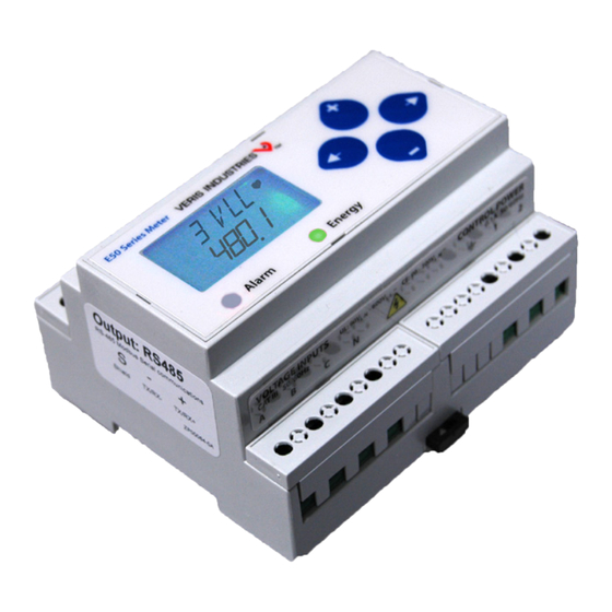
E50B1, E50C2, E50C3
Compact Power and Energy Meter
Product Overview
The E50 DIN Rail Power Meter provides a solution for measuring energy data with a single device. Inputs include
Control Power, CT, and 3-phase voltage. The E50 supports multiple output options, including solid state relay
contacts, Modbus (with or without data logging), and pulse. The LCD screen on the faceplate allows instant output
viewing.
The meter is housed in a plastic enclosure suitable for installation on T35 DIN rail according to EN50022. The E50 can
be mounted with any orientation over the entire ambient temperature range, either on a DIN rail or in a panel. The
meter is not sensitive to CT orientation to reduce installation errors.
Product Identification
Model
E50B1
Pulse Output Only
E50C2
Modbus output, full data set
NEC2014 Article 100
E50C3
Modbus output, data logging
Specifications
Real Power and Energy
Reactive Power and Energy
1
Type of Measurement
Measured AC Voltage
Metering Over-Range
Measurement Input Range
©2014 Veris Industries USA 800.354.8556 or +1.503.598.4564 / support@veris.com
Other companies' trademarks are hereby acknowledged to belong to their respective owners.
Description
Pulse
•
(2 pulses)
•
•
MEASUREMENT ACCURACY
IEC 62053-22 Class 0.2S, ANSI C12.20 0.2%
IEC 62053-23 Class 2, 2%
Current
0.4% (+0.015% per °C deviation from 25°C) from 5% to 100% of
range; 0.8% (+0.015% per °C deviation from 25°C) from 1% to 5% of
range
Voltage
0.4% (+0.015% per °C deviation from 25°C) from 90V
Sample Rate
2520 samples per second
Data Update Rate
1 sec
True RMS up to the 21st harmonic 60 Hz; One to three phase AC
system
INPUT VOLTAGE CHARACTERISTICS
Minimum 90V
UL Maximum: 600V
CE Maximum: 300V
+20%
Impedance
2.5 MΩ
/5 MΩ
L-N
Frequency Range
45 to 65 Hz
INPUT CURRENT CHARACTERISTICS
CT Scaling
Primary: Adjustable from 5 A to 32,000 A
0 to 0.333 VAC or 0 to 1.0 VAC (+20% over-range), rated for use with
Class 1 voltage inputs
Impedance
10.6 kΩ (1/3 V mode) or 32.1 kΩ (1 V mode)
Output
Data Logging
RS-485
Alarm
•
•
•
•
(156V
) for stated accuracy;
L-N
L-L
(347V
)
L-L
L-N
L-N
L-L
TM
•
to 600VAC
L-N
L-L
09141
Advertisement
Table of Contents

Related Manuals for Veris E50C2


Summarization of Contents
Product Overview
Product Identification
Details models E50B1, E50C2, E50C3 and their output options.
Measurement Accuracy
Details accuracy for Real Power, Reactive Power, and Current measurements.
Input Voltage Characteristics
Specifies voltage input range, over-range, impedance, and frequency.
Input Current Characteristics
Defines CT scaling and measurement input impedance.
Specifications
Control Power
Specifies AC and DC control power ratings and ride-through time.
Output Specifications
Details alarm and real energy pulse contact specifications.
RS-485 Port Details
Specifies RS-485 port communication details.
Mechanical Characteristics
Lists weight, IP degree, display, terminal torque, wire size, and DIN rail mounting.
Operating Conditions
Defines operating and storage temperature, humidity, and altitude.
Compliance Information
Lists compliance standards for US, Canada, and CE.
Data Outputs
Full Data Set (FDS)
Lists comprehensive data outputs including power, energy, current, volts, and demand.
Data Logging Features
Details data logging features like RTC, log buffers, interval, and logging modes.
Installation
DIN Rail Mounting
Step-by-step guide for mounting the meter on a DIN rail.
Screw Mounting
Instructions for mounting the meter using screws.
Wiring Diagrams
1-Phase Line-to-Neutral Wiring
Wiring diagram for 1-phase L-N systems with CT input.
1-Phase Line-to-Line Wiring
Wiring diagram for 1-phase L-L systems with CT input.
1-Phase Direct Voltage Connection Wiring
Wiring diagram for 1-phase systems with direct voltage and 2 CT inputs.
3-Phase 3-Wire Wiring
Wiring diagram for 3-phase, 3-wire systems without PT.
3-Phase 4-Wire Wye (Direct Voltage) Wiring
Wiring diagram for 3-phase Wye systems with direct voltage and 3 CT inputs.
3-Phase 4-Wire Wye (3 CT, 3 PT) Wiring
Wiring diagram for 3-phase Wye systems with 3 CT and 3 PT inputs.
Control Power
Control Power Connection Types
Shows wiring for direct connect control power (Line-Line, Line-Neutral, DC).
Control Power Transformer (CPT)
Wiring diagram for using a control power transformer.
Fuse Recommendations
Provides guidance on selecting fuses and circuit breakers for protection.
Alert and Reset Information
Checking Alert Status
Explains how to check for and interpret meter alerts via the wrench icon.
Accessing Unit Information
Details access to unit information like model, OS, and serial number.
Resetting Meter Data
Describes how to reset energy accumulators, demand, and pulse counters.
Accessing Setup Menu
Explains how to access and use the setup menu, including password entry.
UI for Setup
Set Communications Parameters
Configuration of Modbus address, baud rate, and parity.
Set Current Transducer
Configuration for CT input voltage and current transducer size.
Set System Configuration
Selection of system type, CTs, and description.
Set Potential Transformer Ratio
Setting the PT step-down ratio for voltage measurement.
Set System Voltage
Inputting the nominal system voltage for calculations.
System Power Display
Displays theoretical maximum system power, read-only.
UI for Setup (cont.)
Set Phase Loss Parameters
Configuration of voltage and imbalance thresholds for phase loss alerts.
Set Pulse Output Parameters
Configuration of pulse energy per pulse and minimum pulse duration.
Set Demand Interval
Setting the number of sub-intervals and duration for demand calculation.
Set Display Units
Selection between IEC and IEEE display units for measurements.
Set Setup and Reset Passwords
Setting passwords for setup and reset menus.
RS-485 Communications
Daisy-Chaining Devices
Instructions for connecting multiple devices in an RS-485 daisy chain.
RS-485 Terminal Specifications
Torque and wire gauge specifications for terminals.
Data Logging Configuration
Data Logging Setup
Details on setting up data logging time, modes, and buffer management.
Reading Logged Data
Instructions on how to read logged data from the meter.
Data Logging (cont.)
Read/Write Collision Handling
Explains how the meter handles data read/write conflicts during logging.
Modbus Point Map Overview
Supported Modbus Commands
Lists supported Modbus commands like Read Holding Registers and Preset Single Register.
Modbus Map Legend
Defines terms like R/W, NV, Format, Units, Scale, and Range used in the Modbus map.
Modbus Point Map (Integer Data)
Integer Data Points
Details Modbus registers for integer data points like energy consumption and power.
Modbus Point Map (Configuration)
Configuration Registers
Lists Modbus registers for configuration settings like System Type and CT Ratio.
Modbus Point Map (Scale Factors & Phase Loss)
Scale Factor Registers
Explains scale factors used for integer registers and their impact on readings.
Phase Loss Voltage Threshold
Details phase loss voltage and imbalance thresholds and their effect on alerts.
Pulse Output Configuration
Configuration and behavior of kWh pulse output contacts.
Modbus Point Map (Alerts & Logging)
Diagnostic Alert Bitmap
Describes bitmapped alerts for voltage, current, frequency, phase loss, and pulse errors.
Logging Configuration & Status Registers
Registers for logging configuration, status, and date/time clock.
Modbus Point Map (Logging Control)
Logging Read Page Control
Register for selecting which log buffer to read, with warnings about collisions.
Logging Configuration Register
Bit-mapped register for continuous/single shot logging and enabling/halting logging.
Logging Status Register
Bit-mapped register indicating log buffer status, collisions, and RTC changes.
Modbus Point Map (Float Data Pointers)
Log Register Pointers
Specifies the registers for log pointers, typically Real Energy MSR/LSR.
Floating Point Data Registers
Details Modbus registers for floating-point data, including power, voltage, current, and frequency.
Modbus Point Map (Float Data Continued)
Float Data Registers
Continues listing Modbus registers for floating-point data like reactive energy and apparent power.
Logging Interface Registers
Registers related to the logging interface, including data entry points and counts.
Troubleshooting
Wrench Icon Display
Troubleshooting the display of the maintenance wrench icon.
Blank Display After Power
Diagnosing a blank display after applying control power.
Inaccurate Data Display
Troubleshooting inaccurate data readings on the meter display.
Communication Failure
Resolving communication issues with the power meter from a PC.
Need help?
Do you have a question about the E50C2 and is the answer not in the manual?
Questions and answers