Table of Contents
Advertisement
Advertisement
Table of Contents

Related Manuals for Thermo Scientific ALPHA PH 2000


Summary of Contents for Thermo Scientific ALPHA PH 2000
- Page 1 Alpha pH 2000 Processor/Transmitter pH / ORP...
- Page 2 ROSS and the COIL trade dress are trademarks of Thermo Fisher Scientific Inc. U.S. patent 6,793,787. AQUAfast, Cahn, ionplus, KNIpHE, No Cal, ORION, perpHect, PerpHecT, PerpHecTion, pHISA, pHuture, Pure Water, Sage, Sensing the Future, SensorLink, ROSS, ROSS Ultra, Sure-Flow, Titrator PLUS and TURBO2 are registered trademarks of Thermo Fisher.
- Page 3 Preface This manual serves to explain the use of the Alpha pH 2000 series pH/ORP controller/transmitter. The manual functions in two ways, firstly as a step by step guide to help the user operate the instrument. Secondly, it serves as a handy reference guide.
- Page 4 Safety Information The Alpha pH 2000 Controller/ Transmitter shall be installed and operated only in the manner specified in the Instruction manual. Only skilled, trained or authorized person should carry out installation, setup and operation of the instrument. Before powering up the unit, make sure that power source it is connected to, is as specified in the top label.
-
Page 5: Table Of Contents
TABLE OF CONTENTS INTRODUCTION..........................1 ......................1 T THE VERY BEGINNING ..........................1 NTENDED USE ........................ 2 AFETY INSTRUCTIONS ............2 UTTING OUT OF SERVICE ORRECT DISPOSAL OF THE UNIT PRODUCT DESCRIPTION......................3 ........................3 ESCRIPTION OF UNIT ..................4 EASUREMENT AND ONTROL YSTEM... - Page 6 10.3 R ........................39 ETURN OF OODS 10.4 G ................40 UIDELINES FOR ETURNING NIT FOR EPAIR 10.5 M ....................40 AINTENANCE AND LEANING APPENDICES ..........................41 11.1 A 1 – U ................ 41 PPENDIX NIT FUSE AND JUMPER SETTINGS 11.2 A 2 –...
-
Page 8: Introduction
Intended use The Alpha pH 2000 pH/ORP Controller is intended solely for pH or ORP and temperature measurement, as described in this instruction manual. Any other use, or use not mentioned here, that is incompatible with the technical specifications is deemed inappropriate. -
Page 9: Safety Instructions
(see section 8). − The Alpha pH 2000 must not be repaired by the customer. − The Alpha pH 2000 must only be opened to replace the unit fuse or to set the jumper for Pt100/Pt1000 temperature sensor. This work must be carried out only by personnel familiar with the transmitter and who are qualified for such work. -
Page 10: Product Description
PRODUCT DESCRIPTION Description of unit The Alpha pH 2000 is used for measuring pH or ORP and temperature values. The pH or ORP values can be measured using proportional or limit control. The controller is available in two versions, one for panel mounting and one for wall mounting in an enclosure. -
Page 11: Measurement And Control System
Measurement and Control System A typical measurement system consists of: • a pH/ORP process controller • a pH/ORP combination electrode with integrated or separate temperature sensor Pt 100/1000, • an appropriate pH or ORP measurement cable • an immersion, flow or process assembly with or without a potential matching pin (PMP) •... -
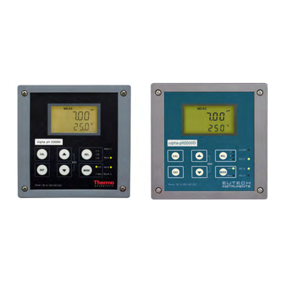
Page 12: Unit Overview
Unit Overview Wall mounting version Panel mounting version... -
Page 13: Display Overview
2.3.1 Display overview The LC display shows two alpha-numerical fields for parameters and measured values as well as various mode and status indicators. Mode indicators: SETUP MEAS – MEAS: Measurement mode ready HOLD – SETUP: Set-up mode – CAL: Calibration mode Status indicators: –... -
Page 14: Led Indicators
LED indicators Relay indicators If REL key is pressed the LED (A, B or W) indicates to which Relay (A, B or Wash) the displayed limit values refer. Relay mode indicators Auto LED lights if relay operation is set to automatic mode. Manu LED lights if relay operation is set to manual mode. -
Page 15: Menu Overview
Menu overview MEAS *CCD “000”= Check calibration parameters (View only mode) CCD “11” = Calibration mode ** SCD “000” = Check setup parameters (View only mode) SCD “22” = Setup mode ENTER ENTER SETUP HOLD SETUP Temperature settings HOLD see section 6.3 SETUP Relay A (set point 1) settings HOLD... -
Page 16: Assembly And Installation
ASSEMBLY AND INSTALLATION Mounting the unit Wall Mounting Version 111.50 [4.39] 144 [5.67] 27.5 [1.08] For Pg13.5 cable glands 24 [.94] 39 [1.54] Pg13.5 (3 pcs.) 78 [3.07] 57.8[2.28] 80 [3.15] Holes for post mounting (4X) Holes for wall mounting (2X) Unit: 6 [.24] MM [INCH]... - Page 17 Panel mounting version Flat gasket 1mm [.04] (to be inserted by customer) Panel cut out UNIT: MM [INCH] Transmitter housing for panel mounting: protection class IP 54 (front), IP 40 (housing)
-
Page 18: Connection Diagram
Connection Diagram Caution: Ensure electrical mains are disconnected before proceeding. Connection for wall mounting version pH/ mV RE LA RELB WASH RE LAY ALAR M R ELAY PT100/ PT1000 Current Current GND +12V HOLD OP 2 AC mains live wire no connection AC mains neutral wire no connection... - Page 19 NOTE: Switch or circuit breaker shall included in the building installation. It shall be in close proximity to the equipment and within easy reach of the operator. It shall be marked as the disconnecting device for the equipment.
- Page 20 Connection for panel mounting version AC mains live wire no connection AC mains neutral wire no connection AC mains protective earth wire 12V Power supply Alarm relay (NO) 12V ground Alarm relay common no connection Alarm relay (NC) Earth ground Wash relay no connection Wash relay...
-
Page 21: Normal Operation
NORMAL OPERATION Measurement mode When the controller is powered on, the display first shows all segments briefly, then the transmitter automatically enters into the Measurement mode. Please note: To guarantee accurate readings the measuring system (controller and sensor) must be calibrated. MEAS The mode indicator “MEAS”... -
Page 22: Calibration Mode
CALIBRATION MODE You can access the Calibration mode directly from the Measurement mode by pressing the CAL key and entering the Calibration security code “11”. Calibration mode may also access via the Setup mode (see section 6.1). Entering Calibration mode MEAS ENTER ENTER... -
Page 23: Ph Calibration
pH Calibration This controller unit features one-point or two-point calibration with five preset buffer sets. Buffer values refer to 25 °C. To calibrate the instrument, you need a standard pH buffer solution that matches one of these values. two-point calibration SETUP MEAS HOLD... -
Page 24: Orp-Mv Calibration
7. Press the ENT key to return to the Measurement mode. Note: If you entered the Calibration mode from the Setup mode, the controller will return to the setup menu. Note: If there is a calibration error the transmitter displays “ERR”. In this case, press the ▲... -
Page 25: Orp -% Calibration
ORP -% Calibration If controller is configured for ORP-% measuring you can perform a calibration at two points using a low concentration sample (20%) and a high concentration sample (80%). To calibrate the controller for ORP %: meas SETUP 59.0 HOLD HOLD HOLD... -
Page 26: View Actual Zero And Slope
View actual zero and slope MEAS 1. While in Measurement mode press the CAL key. The display will prompt you to enter a security code. Leave the security code at “000” (view only mode). 2. Press the ENT key. The display shows the slope in mV (upper value) and the pH reading at 0 mV (zero point, lower value). -
Page 27: Set-Up Mode
SET-UP MODE Enter Setup mode In the Setup mode the controller can be configured to your individual requirements. While in Measurement mode press the ENT key. The display prompts you to enter the security MEAS code. Set the security code with ▲ or ▼ key to: –“SCD22”... -
Page 28: Electrode Offset (Ofs) Sub-Function
Electrode Offset (OFS) sub-function The electrode offset sub-function is only available if the controller is configured for pH measuring. Use this sub-function to set an offset that corrects the readings without removing the electrode from the control system. The setting range is ±120 mV. The controller will add or subtract the offset value from the measured pH and display the corrected value. -
Page 29: Setting Temperature (Set C) Sub - Function
Setting temperature (Set C) sub-function SETUP SETUP SETUP SETUP SETUP HOLD HOLD HOLD HOLD HOLD SETUP SETUP SETUP HOLD HOLD HOLD 1. Select the “SET °C°F” sub-function, then press the ENT key. 2. Selecting temperature unit: press the ▲ or ▼ key to select the desired temperature unit “°C”... -
Page 30: Control Relay A/Control Relay B (Sp1/Sp2) Sub-Function
Control Relay A/Control Relay B (SP1/SP2) sub-function The SP1 sub-function determines the operating parameters for Relay A; while SP2 defines the operating parameters for Relay B. Since these groups have the same set-up parameters, they are described together. SETUP SETUP SETUP SETUP HOLD... - Page 31 the relay for the number of seconds (0 to 1999 seconds) you select. Press the ENT key to confirm your setting. Note: You can set a time delay for each relay, which stops the relay from switching on the moment the set point is exceeded. This controller lets you set a 0 to 1999 second time delay before your relay activates.
-
Page 32: Controller (Cntr) Sub-Function
Controller (CNTR) sub-function The CNTR sub-function determines the controller’s parameters. SETUP SETUP HOLD HOLD SETUP SETUP l.ct HOLD HOLD SETUP HOLD SETUP SETUP SETUP p/pI HOLD HOLD HOLD SETUP HOLD SETUP SETUP HOLD HOLD SETUP HOLD SETUP SETUP SETUP HOLD HOLD HOLD SETUP... - Page 33 - OFF = controller off Use control Off to operate controller as a monitor only or to prevent relays from switching. - L.CT = limit value control (on/off control). Use limit control with pumps or values for fast response - P/PI = proportional/integral control Use proportional control to operate your pumps smoothly or for precise control of proportioning valves.
-
Page 34: Current Output 1 Sub-Function
Setting the proportional range: press the ▲ or ▼ key to set the proportional range (setting range: 10 to 500%). Press the ENT key to confirm your setting. Setting the pulse frequency: press the ▲ or ▼ key to set the pulse frequency (setting range: 60 to 120 pulses per minute). -
Page 35: Current Output 2 Sub-Function
Current Output 2 sub-function In this sub-function you set the current output range of the transmitter for temperature values. SETUP SETUP SETUP SETUP cur.2 HOLD HOLD HOLD HOLD SETUP SETUP SETUP HOLD HOLD HOLD 1. Select the “CUR.2” sub-function, then press the ENT key. 2. -
Page 36: Wash Relay (Wash) Sub-Function
Wash relay (WASH) sub-function In this sub-function you set the parameters for the wash relay. SETUP SETUP SETUP SETUP SETUP HOLD HOLD HOLD HOLD HOLD SETUP HOLD SETUP HOLD 1. Select the “WASH” sub-function, then press the ENT key. 2. Enabling/disabling wash function: press the ▲ or ▼ key to enable (WASH ON) or disable (WASH OFF) wash function. -
Page 37: Configuration (Cnfg) Sub-Function
Configuration (CNFG) sub-function In this sub-function you configure the controller to suit your requirements. SETUP SETUP SETUP SETUP SETUP HOLD HOLD HOLD HOLD HOLD SETUP HOLD SETUP HOLD SETUP HOLD SETUP HOLD SETUP HOLD SETUP HOLD SETUP SETUP SETUP HOLD HOLD HOLD SETUP... - Page 38 – “PH SY” = pH measurement with symmetrical input – “PH ASY” = pH measurement with asymmetrical input – “ORP % SY” = ORP-% measurement with symmetrical input – “ORP % ASY” = ORP-% measurement with asymmetrical input – “ORP mV SY” = ORP-mV measurement with symmetrical input –...
-
Page 39: Calibration (Cal) Sub-Function
8. Resetting the controller settings to factory defaults: The display shows “NO DEF”. Press the ▲ or ▼ key to select: – “NO DEF” = keeps old values active, when confirmed with ENT. – “FCT DEF” = resets all settings to factory defaults, when confirmed with ENT. -
Page 40: Relay Modes
RELAY MODES You can control devices connected to Relay A, Relay B or wash relay via the front panel of the transmitter. In Automatic mode, the controller’s set point values activate the relays. In Manual mode, you can manually turn “on” and “off”... -
Page 41: Manual Relay Mode
Manual relay mode In manual relay mode, you can manually turn “on” and “off” the control devices connected to Relay A, Relay B or Wash relay. 1. While in Measurement mode press the MODE key. 2. The display prompts you to enter the security code. Press the ▲ or ▼ key to set security code to “22”. -
Page 42: Technical Specifications
TECHNICAL SPECIFICATIONS General Specification Alpha pH 2000 Controller / Transmitter pH Range -2.00 to 16.00 pH Resolution & Accuracy 0.01 pH & ± 0.01 pH mV Range 0 to 100% or -1000 to 1000 mV Resolution & Accuracy 0.1% or 1 mV / ± 1 mV Temperature -9.9 to 125... -
Page 43: Specifications For Wall Mount Version
EMC Specifications Emitted Interference EN 61 326 Immunity to Interference EN 61 326 Environmental Conditions Ambient Temp. Operating -10 to 50 C (14 to 122 Range Rel. Humidity 10 to 95% (non-condensing) Power Supply Input 80 to 250 VAC/DC 48/62 Hz Main Fuse 250 mA anti-surge Pollution Degree... -
Page 44: Specifications For Panel Mount Version
Specifications for panel mount version Electrical Data And Connections Signal output Two 0/4 to 20 mA outputs for pH/mv and temperature , galvanically isolated Max.600 Ω Load pH / ORP Input BNC (10 Impedance) Connection terminal (1 x 3-pin; 1 x 9-pin & 1 x 19-pin terminal blocks) Mechanical Specifications... -
Page 45: Accessories
ACCESSORIES Replacement Unit Product Description Thermo Scientific Order Code Alpha pH 2000 pH/ORP Controller/Transmitter, wall mount TSPHCTP2000W version Alpha pH 2000 pH/ORP Controller/Transmitter, panel TSPHCTP2000P mount version Product Description Eutech Instruments Order Code Alpha pH 2000 pH/ORP Controller/Transmitter, wall mount... -
Page 46: General Information
GENERAL INFORMATION 10.1 Warranty This Controller transmitter is supplied with a one-year warranty against significant deviations in material and workmanship from date of purchase and a six-month warranty for probe. Each instrument will have a warranty card with a specific serial number. -
Page 47: Guidelines For Returning Unit For Repair
10.5 Maintenance and Cleaning Maintenance The Alpha pH 2000 contains no user repairable components. Please contact Eutech Instruments or its distributor if there is any problem with the unit. Cleaning To remove dust, dirt and spots, the external surfaces of the controller may be wiped... -
Page 48: Appendices
APPENDICES 11.1 Appendix 1 – Unit fuse and jumper settings − Caution! Before opening the unit to replace the unit fuse or to set the jumper for Pt 100 / Pt 1000 temperature sensor, make sure the mains cable is separated from the power supply. Wall mounting version C101 REG1... - Page 49 Panel mounting version R55 R5 1 R5 3 R7 0 R7 8 C102 C8 7 C7 8 C114 C113 R96 C7 5 Q 15 C117 C1 22 R5 6 D1 3 R6 0 R6 2 R7 5 C8 6 C109 C110 C115 Q 10 C8 0...
-
Page 50: Appendix 2 - P Hbuffer Values At Various Temperatures
11.2 Appendix 2 – pH buffer values at various temperatures The following table shows the various pH values at different temperature of the solution during calibration. Tempera pH 1.00 pH 4.01 pH 6.86 pH 7.00 pH 9.00 pH 9.18 pH 10.01 ture ( 0.96 4.01... -
Page 51: Appendix 3 -Simple Explanation On The Function Of Hysterisis
11.3 Appendix 3 –Simple explanation on the function of hysterisis S P 1 S e t t o L O S P 2 S e t t o H I R E L A Y O N R E L A Y O F F 4 . -
Page 52: Appendix 4 - General Instructions Concerning Controller Setting
11.4 Appendix 4 – General instructions concerning Controller Setting 11.4.1 Control characteristic of Controllers used as limit value switch MIN Function MAX Function 100 % 50 % + Xw - Xw SP 1 SP 2 Xp = 0 Xp = 0 11.4.2 Control characteristic of P-Controller as proportional controller MIN Function MAX Function... -
Page 53: Controller Signal Of Pulse Length Controllers
11.4.4 Controller signal of Pulse length Controllers Relay Pulse Length T Time [s] The output relay of the pulse length controller is clock-timed. The switching period T remains constant. Depending on the divergence from the limit value, the switch-on time t is increased or decreased in accordance with the proportional range Xp. -
Page 54: Controller Signal Of Pulse Frequency Controllers
11.4.5 Controller signal of Pulse Frequency Controllers Relay Pulse Length T Time [s] The output relay of the pulse frequency controller is clock-timed. The pulse duration t remains constant at 250mS. Depending on the divergence from the limit value, the frequency ( 1 / T ) is increased or decreased in accordance with the proportional range Xp. -
Page 55: Appendix 5 - Abbreviations Used In Menu Displays
11.5 Appendix 5 – Abbreviations used in menu displays Abbreviation Meaning Abbreviation Meaning MEAS Measurement CUR.1 Output current 1 Calibration CUR.2 Output current 2 Enter Output signal Offset 4 - 20 4 to 20mA C.CD Calibration Security Code 0 - 20 0 to 20 mA S.CD Setup Security Code... - Page 56 Water Analysis Instruments North America 166 Cummings Center Beverly, MA 01915 USA Toll Free: 1-800-225-1480 Tel: 1-978-232-6000 Dom. Fax: 1-978-232-6015 Int’l Fax: 978-232-6031 Europe P.O. Box 254, 3860 AG Nijkerk Wallerstraat 125K, 3862 CN Nijkerk, Netherlands Tel: (31) 033-2463887 Fax: (31) 033-2460832 Asia Pacific Blk 55, Ayer Rajah Crescent #04-16/24, Singapore 139949...
Need help?
Do you have a question about the ALPHA PH 2000 and is the answer not in the manual?
Questions and answers