
Related Manuals for Thermo Scientific PRO902C


Summary of Contents for Thermo Scientific PRO902C
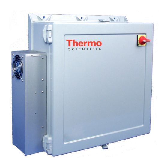
- Page 1 PRO902C Instruction Manual Dilution Probe Conditioning Assembly & Remote Probe Controller Assembly Part Number 111981-00 16Aug2007...
- Page 2 © 2011 Thermo Fisher Scientific Inc. All rights reserved. Specifications, terms and pricing are subject to change. Not all products are available in all countries. Please consult your local sales representative for details. Thermo Fisher Scientific Air Quality Instruments 27 Forge Parkway Franklin, MA 02038 1-508-520-0430 www.thermoscientific.com/aqi...
- Page 3 WEEE Compliance This product is required to comply with the European Union’s Waste Electrical & Electronic Equipment (WEEE) Directive 2002/96/EC. It is marked with the following symbol: Thermo Fisher Scientific has contracted with one or more recycling/disposal companies in each EU Member State, and this product should be disposed of or recycled through them.
-
Page 4: Table Of Contents
PRO902C MANUAL PRODUCT DESCRIPTION Introduction ..................... 1-1 PRO902 description ..................1-1 Dilution probe conditioning assembly hardware ..........1-2 1.3.1 Probe enclosure ................... 1-2 1.3.2 Enclosure heater .................. 1-2 1.3.3 Valve manifold and dilution air regulator..........1-3 1.3.4 Heated filter, dilution eductor, and probe barrel assembly...... 1-3 1.3.5 Heat exchanger and drain valve assembly .......... - Page 5 The PRO902C and remote probe controller assembly are shipped ready for operation. Immediate inspection of the PRO902C and remote probe controller assembly should follow upon receipt. Inventory of the container should be checked against the enclosed packing list. If there is a shortage of items, the operator should immediately contact TFS.
- Page 7 PRO902C MANUAL PRODUCT DESCRIPTION Introduction ..................... 1-1 PRO902 description ..................1-1 Dilution probe conditioning assembly hardware ..........1-2 1.3.1 Probe enclosure ................... 1-2 1.3.2 Enclosure heater .................. 1-2 1.3.3 Valve manifold and dilution air regulator..........1-3 1.3.4 Heated filter, dilution eductor, and probe barrel assembly...... 1-3 1.3.5 Heat exchanger and drain valve assembly ..........
- Page 8 PRO902C MANUAL 3.2.1 Stack temperature extremes ..............3-2 3.2.2 Ambient temperature extremes.............. 3-2 3.2.3 Process pressure ................... 3-2 General installation................... 3-2 3.3.1 Dilution probe conditioning assembly............ 3-2 3.3.2 Air supply..................... 3-5 3.3.3 Sample and calibration gas lines ............3-5 3.3.4 Vent line ....................3-5 3.3.5 Power ....................
- Page 9 4.11.9 High span reading ................. 4-9 ASSEMBLY REPAIR....................5-1 Obtaining replacement parts ................5-1 Spare parts list, CTL902C ................5-1 Spare parts list, PRO902C................5-2 Extended Parts List, PRO902C................. 5-3 Recommended tools ..................5-5 LIST OF DRAWINGS ....................6-1 LIST OF FIGURES Dilution probe assembly ...................
- Page 10 PRO902C MANUAL Probe head flow test configuration..............4-5 4.10 Eductor vacuum test configuration ..............4-6 LIST OF TABLES 1.4.2 Wiring umbilical table..................1-6 3.4.1 Setup menu parameters ..................3-7 3.4.2 Operation setup menu..................3-8 Rev 6.0 August 16, 2007...
-
Page 11: Product Description
PRO902C description The PRO902C dilution probe conditioning assembly is a three-part package. Part one is the stack or duct mounted dilution probe conditioning assembly, part two is the wiring and tubing umbilicals, and Part three is the remote controller assembly. The dilution probe conditioning assembly draws, conditions, and dilutes the process emissions to be transported for analysis. -
Page 12: Dilution Probe Conditioning Assembly Hardware
Remote probe controller assembly: please refer to the 7000 series probe controller drawings. Dilution probe conditioning assembly hardware The PRO902C dilution probe conditioning assembly consists of eight subassemblies used to condition, analyze, and transport the sample: 1. Probe enclosure. 2. Enclosure heater. -
Page 13: Valve Manifold And Dilution Air Regulator
PRO902C MANUAL 1.3.3 Valve manifold and dilution air regulator The air valve manifold provides distribution of the box purge and heated filter purge air, and a place to conveniently mount the four valves for the Probe conditioning assembly. The four valves include: SV-1, the calibration valve used to inject calibration gas in the heated filter chamber;... -
Page 14: Heat Exchanger And Drain Valve Assembly
PRO902C MANUAL 1.3.5 Heat exchanger and drain valve assembly The heat exchanger and drain valve are located on the left wall of the dilution probe ® Assembly. A thermoelectric cooled Teflon block, a moisture collection reservoir, an ambient exposed aluminum heat sink, and purge valve comprise the heat exchanger system. -
Page 15: Valve Controller (Watchdog) Module
PRO902C MANUAL The power requirement is 120VAC, 800 watts, 60 Hz. AC hot is supplied to disconnect DC1. From DC1, AC hot is distributed to the valve controller watchdog module, the heat exchanger control module, the enclosure heater, and the enclosure utility light and outlet. TB- 2 supplies power and control for the heat exchanger temperature control. -
Page 16: Remote Probe Controller Assembly
PRO902C MANUAL analyzers in the analyzer rack with diluted sample. 1.4.2 Wiring Umbilical Table Pair Number Function Signal Heat exchanger RTD signal 4-20 milliamp Heat exchanger control signal 0-24 VDC pulse modulation Heated filter RTD signal 4-20 milliamp Heated filter control signal... -
Page 17: Temperature Controllers
For more information, please refer to the Watlow Series 93 User's Manual. Specifications The PRO902C dilution probe conditioning assembly was designed to operate within the following specifications: Power requirements: 115 VAC, 800 Watts Power connection: CSA/UL Approved screw terminal. - Page 18 PRO902C MANUAL Sample flow: approx. 100-300 cc/minute Dilution flow: approx. 5-10 L/minute Eductor pump assembly: Sample flow: approx. 100 cc/minute Dilution flow: approx. 5 L/minute Heat Exchanger: Cooler block temperature: 7.2°C 5°C (45°F - 50°F) Heated eductor/filter Body temperature: 140.5°C ±...
-
Page 19: Theory Of Operation
The PRO902C delivers a 4-20 mADC oxygen output signal for data retrieval and produces a closure (alarm) for low system air pressure. -
Page 20: Sampling Mode
2 to 5 minutes, depending upon application, which is adequate for most process control and environmental monitoring requirements. System response time requirements have been met with the PRO902C dilution probe conditioning assembly by a three-step process. Upon extraction from the stack, the process sample gas is filtered, dried via the heat exchanger, and diluted. -
Page 21: Purge Mode
PRO902C MANUAL ® Once the filtered sample gas enters the Teflon heat exchanger cooling block, any condensable or entrained liquids are condensed and collected in the liquid reservoir at the lower extreme of the cooling block. The heat from the cooling block is removed using a thermoelectric cooler and then transferred to the externally mounted aluminum heat sink. -
Page 22: Calibration Mode
PRO902C dilution probe conditioning assembly calibration gas inlet. The gas enters the dilution probe through the calibration gas solenoid valve (V-1) and then into the filter body through the purge/calibration gas inlet. -
Page 23: Installation And Operation
Performance Specification Two (2) is followed. The PRO902C dilution probe conditioning assembly is installed on a four (4) inch pipe flange. The pipe flange must be installed on a pipe nipple extending six (6) inches from the outer wall of the stack. -
Page 24: Limitations At The Probe Site
All maintenance can be performed from the front of the unit. Limitations at the probe site The placement of the PRO902C dilution probe conditioning assembly is important to achieve its maximum reliability. 3.2.1 Stack temperature extremes ®... - Page 25 PRO902C MANUAL Conditioning assembly installation Install the conditioning assembly on the four (4) inch flange using a proper flange gasket and four 1/2 inch X 1-3/4 inch stainless steel bolts: please see Figure 3.1. Probe head removal Open the conditioning assembly door and locate the dilution probe head. Carefully cut and remove the shipping tie wrap from the probe head and support bracket.
-
Page 26: Probe Barrel Assembly
PRO902C MANUAL TOP CENTER .5 In 1.0 In MOUNTING GASKET Figure 3.3 Probe Barrel Assembly Probe head installation NOTE: Before initial installation of the dilution probe assembly, and after any probe head maintenance, the tests described in Sections 4.9 and 4.10 of this manual should be performed. The probe pre-test verifies that the probe assembly is leak free and has the proper flow rates. -
Page 27: Air Supply
NOTE: The sample vent/eductor exhaust should never be restricted or pressurized. 3.3.5 Power A standard 115VAC, 15A service is required to operate the PRO902C dilution probe conditioning assembly. Service must be supplied using 12 AWG minimum. For long runs Rev 6.0... -
Page 28: Control And Data Lines
PRO902C MANUAL where voltage drops may occur, 10 AWG may be used. Connect the power to disconnect switch DC1, TB-1 and the grounding screws (please refer to the site-specific wiring drawings). DC1 is a UL and CSA approved disconnect switch rated for 10 AWG wire, 20 Amps AC. - Page 29 PRO902C MANUAL 1. Remove the Watlow controllers from the front panel and check the dip switches on the backs of the controllers: both switches should be in the “on” position. 2. Reinstall the temperature controllers and apply power to the remote probe controller assembly via the power switch located at the rear of the chassis.
- Page 30 PRO902C MANUAL 5. Please refer to Table 3.4-2, below, for parameter set points for each controller. Enter the operation menu by pressing the (Advance) key. The controller is in the operation menu when “Pb1” is displayed on the lower window. To proceed to the next parameter, press the ...
-
Page 31: Madc Current Output Calculation
4% oxygen headroom when monitoring atmospheric oxygen levels. The 25% full-scale value prevents input circuit saturation when atmospheric levels are pulled into the PRO902C dilution probe conditioning assembly during periodic maintenance. A full-scale value of 10% oxygen is used when lower levels of oxygen are typically present in the process. -
Page 32: City Technology O Sensor Alignment
PRO902C MANUAL In this example, 17.376 mA equals 20.9% oxygen: ( 0.836 * 16) + 4 = 17.376 mADC output Four (4) mA has been set to equal 0% oxygen and 20 mA has been set to equal 25% oxygen (full-scale). -
Page 33: Absolute Pressure Transducer Checkout Procedure
PRO902C MANUAL 25 % O full-scale 20.9 % O span gas concentration 20.9 % O ------------- = 0.836 or 83.6% of full-scale 25 % O ( 0.836 * 16) + 4 = 17.376 mADC output After the cell has stabilized, adjust the span potentiometer (R18 on the remote O PCA) to the calculated mADC output (please refer to figure 3.7-1 for span potentiometer... -
Page 34: Remote Probe Controller Interface Board Setup
PRO902C MANUAL Figure 3.8-1 Remote Probe Controller Interface Board Setup At the analyzer rack valve panel, turn the cal valve and the O2 zero switches to “ON”. Locate the interface printed circuit card and connect an ammeter in series with connector J1, pin 15 (O2 input signal) and another ammeter in series with connector J5, pin 2 (O2 output signal). -
Page 35: Remote Probe Controller Electronics
– 4 X 25 = correct meter reading where mA reading is the input milliamps at J1, pin 15, of the interface board. The oxygen system on the PRO902C is now calibrated and ready for an initial calibration. -
Page 36: Maintenance
General The following procedures are designed to allow the maintenance technician to accomplish all necessary maintenance procedures on the PRO902C dilution probe conditioning assembly. With the exception of changing the heated filter element, none of these procedures are to be... -
Page 37: Quartz Orifice Replacement
PRO902C MANUAL Inspect the filter body and cap for particulate accumulation around the filter seats. Clean the filter body and seat by wiping with a soft cloth. Lubricate the cap o-ring with a light coating of silicone based high vacuum grease. -
Page 38: Orifice Holder Assembly Removal
PRO902C MANUAL Orifice holder assembly removal Remove the probe head as described in section 4.5. Remove the eductor assembly housing insulated cover. Remove the four (4) spring screws and remove the flat washers and springs. Remove the eductor assembly top cap. -
Page 39: Probe Head Leak Test
PRO902C MANUAL gasket with a fresh, thin coat of silicone high vacuum grease. Do no let any grease get in the gasket opening. Reassemble the eductor assembly in the reverse order of disassembly, being sure to align the block passages with the gasket opening. -
Page 40: Probe Head Flow Test
PRO902C MANUAL Probe head flow test The dilution probe may be supplied with various jets to accomplish different dilution ratios. Please refer to the site-specific system flow diagram to obtain the proper flow rates. Connect a mass flow meter in-line to the eductor exhaust (outlet) port (eductor outlet flowmeter as shown in Figure 4.9). -
Page 41: Trouble Shooting
PRO902C MANUAL EDUCTOR EXHAUST DILUTION AIR IN 30 PSI HAND VACUUM PUMP Figure 4.10 Eductor Vacuum Test Configuration 4.11 Trouble shooting 4.11.1 Zero drift - full system Zero drift is independent of the dilution system, as any dilution of a zero gas will still cause a zero indication on the analyzer. -
Page 42: High Sample Flow Rate
PRO902C MANUAL Possible problem - Plugged orifice. Change orifice Corrective action: Possible problem - Leak around filter cap. Clean o-ring and apply high vacuum grease. Replace o-ring. Corrective action: Possible problem - Leak at probe connection to filter body. Clean probe tip and o-rings area. Apply silicone grease to probe and o- Corrective action: rings. -
Page 43: High Flow Rate At The Eductor Exhaust
PRO902C MANUAL Possible problem - Restricted eductor exhaust tubing. Check internal and external exhaust vent tubing for restrictions. Corrective action: Possible problem - Pressure Regulator not adjusted correctly or defective. Adjust or replace regulator. Corrective action: 4.11.6 High flow rate at the eductor exhaust Possible problem - Regulator pressure set too high. -
Page 44: High Span Reading
PRO902C MANUAL Replace filter element. Corrective action: Possible problem - Sample jet plugged. Replace jet. Corrective action: Possible problem - Leak at filter body cap. Clean or replace filter cap o-ring. Check purge/calibration gas inlet Corrective action: filter. Possible problem - Leak at probe/filter connections. -
Page 45: Obtaining Replacement Parts
PRO902C MANUAL RETURNING ASSEMBLIES FOR REPAIR Should it become necessary to return any assembly, sub-assembly, or component for repair or replacement, contact the factory prior to shipment for specific information such as: return authorization number, shipping instructions, price, time to repair, etc. Also include pertinent facts describing the nature of the problem. -
Page 46: Spare Parts List, Pro902C
PRO902C MANUAL Spare parts list, PRO902C 00002968 Holder, Assembly, Orifice, Quartz, Dry, Torlon 17010069 PCA, O2 Driver 2FO Citicell 0-25% 22000009 Controller Assembly, Watchdog/Valve 22000010 CONTROLLER ASSEMBLY, HEATED FILTER 25501002 GASKET, EDUCTOR 25503002 O-RING, #006 25503003 O-RING, #14 25503011 O-RING, EDUCTOR JET... -
Page 47: Extended Parts List, Pro902C
PRO902C MANUAL Extended Parts List, PRO902C 00300061 Support, Heated Filter, Aluminum 07020001 IFED, Assy, Dry, w/o Probe Barrel 26010016 Housing, Filter, Dry basis 26010009 Filter Body, Dry basis 2.5” 26010002 Eductor, Cap, (side) AFB 26010003 Eductor, Cap, (top) 26010012 Holder, Orifice, Quartz, Dry, Torlon 26010018 Nut, Filter Cap –1/2”, Torlon... - Page 48 PRO902C MANUAL 00800029 Shroud, Fan 00300009 Bracket, Capacitor, Mntg. 15121509 Cap., 15Kmf 16V Radial 17010072 PCA, Controller, TE Cooler 21001164 Conn, Flange, MT Recp 16pin Male 21002032 Conn, Recpt, 3 Pin Molex 21031000 Terminal, Socket Molex 18-22AWG 21031003 Terminal, Pin, Crimp, 16-18AWG 21090010 Cable, Clamp for 16 pin .453 Dia Cable Max...
-
Page 49: Recommended Tools
PRO902C MANUAL 26232312 Fitting, SS 1/8MPT-1/4T Elbow 26246812 Fitting, SS 1/8MPT-1/4TT Tee Run 26262010 Fitting, SS 1/8MPT Plug 26346312 Fitting, Tef, Tee, 1/8T-1/4T-1/8T 26346320 Fitting, Tef, 1/4TTT TEE 26413312 Fitting, KY, 1/8T-1/4T TB Stub 26711210 Fitting, SS SW 1/8FPT-10x32MPT 28254002... -
Page 50: List Of Drawings
XXXX7151 2 OF 2 SOURCE DILUTION PROBE ASSEMBLY LIST OF DRAWINGS DRAWING REV SHEET # DESCRIPTION NUMBER 07020001 1 OF 2 IFED, ASSY, DRY, W/O PROBE 26010019 1 OF 1 EDUCTOR ASSEMBLY, 10L, TORLON 26010021 1 OF 1 EDUCTOR ASSEMBLY, 5L, TORLON 00002968 1 OF 1 HOLDER, ASSEMBLY, ORIFICE, QUARTZ,... - Page 51 Appendix A Warranty Seller warrants that the Products will operate or perform substantially in conformance with Seller's published specifications and be free from defects Warranty in material and workmanship, when subjected to normal, proper and intended usage by properly trained personnel, for the period of time set forth in the product documentation, published specifications or package inserts.
- Page 52 they were not designed, (v) causes external to the Products such as, but not limited to, power failure or electrical power surges, (vi) improper storage and handling of the Products or (vii) use of the Products in combination with equipment or software not supplied by Seller. If Seller determines that Products for which Buyer has requested warranty services are not covered by the warranty hereunder, Buyer shall pay or reimburse Seller for all costs of investigating and responding to such request at Seller's then...
Need help?
Do you have a question about the PRO902C and is the answer not in the manual?
Questions and answers