Sign In
Upload
Download
Table of Contents
Contents
Add to my manuals
Delete from my manuals
Share
URL of this page:
HTML Link:
Bookmark this page
Add
Manual will be automatically added to "My Manuals"
Print this page
×
Bookmark added
×
Added to my manuals
Manuals
Brands
Carrier Manuals
Air Conditioner
AirV 68RV14112A
Service manual
Carrier AirV 68RV14112A Service Manual
Hide thumbs
1
2
3
4
5
Table Of Contents
6
7
8
9
10
11
12
13
14
15
16
17
18
19
20
21
22
23
24
25
26
27
28
29
30
31
32
33
34
35
36
37
38
39
40
41
42
43
44
45
46
47
48
49
page
of
49
Go
/
49
Contents
Table of Contents
Troubleshooting
Bookmarks
Table of Contents
Service Manual
Table of Contents
Figure Number
Paragraph Number
Description
Introduction
Serial Number Identification
Design Change Descriptions
Figure 1-1 Model/Serial Number Plate (Typical)
Table 1-1 Model Chart
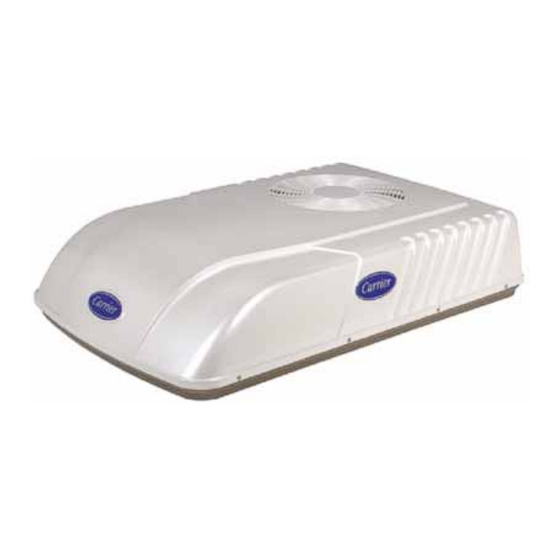
Figure 1-2 Roof Unit Component Identification
Table 1-2 Additional Support Manuals
Figure 1-3 Ceiling Unit Component Identification (Free-Blow)
Figure 1-4 Component Identification - Low Profile - Upper Unit
Figure 1-5 Component Listing-Ceiling Unit for Ducted Systems
Figure 1-6 Ducted System Air Flow Arrangement
Figure 1-7 Serial Number Locations
Airv SYSTEM COMPONENT SPECIFICATIONS
Refrigerant Charge
Compressor - 115 Volts, 60 Cycles, 1 Phase
Compressor - 220 Volts, 50 Cycles, 1 Phase
Thermostat Range (All Free Blow Units)
Start-Up
Refrigerant Cycle-Standard System
Figure 1-8 Refrigerant Flow Schematic (Standard System)
Refrigerant Cycle - Heat Pump
Cooling
Heating
Troubleshooting
No Power to Unit
Ducted Unit will Not Operate
Ducted Unit will Not Cool
Compressor Power Supply Open
Compressor Runs but Cycles, Fan Operating Erratically
Cycles on Compressor Overload
Insufficient Cooling, Cooling Air Not Adequate
Condenser Air Not Adequate
Insufficient Cooling
Compressor Flooding
Heater Cycles on Limit Switch (Heat/ Cool Version Only)
Air Sweep Not Working (Free Blow Version Only)
Water Leakage
Inadequate Heat (Free-Blow Heat Only)
Inadequate Heat (Heat-Pump)
Clearing Diagnostic Alarms
Table 2-1 System Self-Diagnostics Function (Ducted Remote)
Service and Maintenance
Preventative Maintenance
Service - General
Ceiling Unit - Free Blow Systems
Filter Removal
Ceiling Grill Removal
Ceiling Panel Removal
Master Control Switch
Air Sweep Switch Removal
Figure 3-2 Ceiling Grill - Free Blow
Figure 3-3 Ceiling Panel Assembly
Figure 3-4 Ceiling Panel with Heat Option
Figure 3-5 Control Box Assembly - Free Blow
Indoor Thermostat Removal
Air Sweep Removal
Heat Strip Assembly Removal
Figure 3-6 Indoor Thermostat
Figure 3-7 Air Sweep Motor
Figure 3-8 Heat Strip Assembly
Figure 3-9 Filter Removal - Ducted Unit
Figure 3-11 Control Box & PCB Cover
Figure 3-12 Control Box Assembly - Ducted
Figure 3-13 Main/Display Pcb's
Figure 3-16 Control Box Removal
Figure 3-17 Water Cover Removal
Compressor Replacement
Figure 3-18 Upper Scroll Assembly
Figure 3-19 Motor Assembly
Figure 3-20 Spring Clamp Removal
Figure 3-21 Motor Clip Removal
Figure 3-22 Condenser Fan Removal
Figure 3-23 Blower Wheel
Figure 3-24 Condenser with Motor Assembly & Compressor
Evaporator Blower Wheel Adjustment or Removal
Figure 3-25 Set-Up for Discharging a Capacitor
Capacitor Troubleshooting
Figure 3-26 Cover Assembly - Low Profile
Figure 3-27 Upper Scroll Assembly Locking Tabs (B.) & Screw Locations (C.)
Figure 3-28 Upper Scroll Assembly Keeper Tab Release
Service - Upper Unit - Low Profile
Figure 3-29 Upper Scroll & Control Box Cover Removed
Figure 3-30 Condenser Fan Assembly & Retaining Ring
Figure 3-31 Condenser Fan Motor & Fan Assembly Stop
Figure 3-32 Condenser Fan Motor & Fan Assembly Tab
Condenser Motor Removal
Figure 3-33 Condenser Motor Ground
Figure 3-34 Evaporator Motor Locking Tabs
Figure 3-35 Evaporator Motor/Blower Assembly in Cradle
Compressor Replacement
Figure 3-36 Evaporator Blower Wheel (Flush with End of Motor Shaft)
Figure 3-37 Control Box Assembly with Capacitor
Figure 3-38 Remote Control Components
Figure 3-39 Remote Control PCB (FR9 Location)
Thermostat Installation and Start-Up Instructions (Wall Mounted)
Check Thermostat Operation
Temperature Display
Timeguard Timer
Cycle Timer
Minimum on Timer
Error Messages
Figure 3-40 Wall Thermostat Wiring Diagram - Cool Only Model
Figure 3-41 Wall Thermostat Wiring Diagram - Heat/Cool Model
Wiring Schematics
Introduction
Figure 4-1 Upper Unit Schematic - Standard & HC
Figure 4-3 Ceiling Unit Schematic - Cooling Only
Advertisement
Quick Links
1
Service Manual
2
Serial Number Identification
3
Figure 1-2 Roof Unit Component Identification
Download this manual
Transport Air Conditioning
Transport Air Conditioning
R
R
2P
BLK
1
BLU
2
GRN/YEL
WHT
EVAP.
WHT
YEL
C
1
2
Rooftop Air Conditioning Systems
T--298 Rev D
BRN
WHT
F
C
H
RED
RED
BLU
R
PTC
BLU
S
SERVICE MANUAL
for
MODEL AirV
Table of
Contents
Previous
Page
Next
Page
1
2
3
4
5
Advertisement
Table of Contents
Troubleshooting
TROUBLESHOOTING
21
Figure 3-25 Set-Up For Discharging a Capacitor
33
Need help?
Do you have a question about the AirV 68RV14112A and is the answer not in the manual?
Ask a question
Questions and answers
Related Manuals for Carrier AirV 68RV14112A
Air Conditioner Carrier 62DA User's Information Manual
Vertical or horizontal dedicated 100% outdoor air unit with optional gas heat (9 pages)
Air Conditioner Carrier Transicold 68RF50 Neoplan-LA Operation And Service Manual
Carrier bus air conditioning unit (44 pages)
Air Conditioner Carrier 68G5-105 Series Operation & Service Manual
68g5-105 series; (56 pages)
Air Conditioner Carrier 68RV11302A Service Manual
(49 pages)
Air Conditioner Carrier AirV 68RV11112A Service Manual
Rooftop air conditioning systems (20 pages)
Air Conditioner Carrier 40GRQ Installation Instruction
High- wall ductless split system (14 pages)
Air Conditioner Carrier 619FB Service Manual
High---wall ductless split system, sizes 009 to 018 (94 pages)
Air Conditioner Carrier 61WG 020 Installation, Operation And Maintenance Instructions
Pro-dialog water-cooled/condenserless liquid chillers/water-sourced heat pumps with or without integrated hydronic module (56 pages)
Air Conditioner Carrier PrimeLINE 69NT40-561-200 Operation And Service Manual
Container refrigeration units (184 pages)
Air Conditioner Carrier 38MGQ Series Service Manual
Multi-zone ductless split system (76 pages)
Air Conditioner Carrier 538PR Owner's Manual
(10 pages)
Air Conditioner Carrier 69NT40-561-201 Operation & Service Manual
Evergreen container refrigeration units (117 pages)
Air Conditioner Carrier DE 60HIDU230X5 Installation Manual
High static pressure duct type air conditioner (37 pages)
Air Conditioner Carrier AirV 68RV14113A Service Manual
Rooftop air conditioning systems (20 pages)
Air Conditioner Carrier bryant 619PHB Owner's Manual
Ductless unit split system sizes 09, 12 and 18 (16 pages)
Air Conditioner Carrier 68RM35-610 Operation And Service
Micromax / mchx rear mount air conditioning unit (59 pages)
Table of Contents
Save PDF
Print
Rename the bookmark
Delete bookmark?
Delete from my manuals?
Login
Sign In
OR
Sign in with Facebook
Sign in with Google
Upload manual
Upload from disk
Upload from URL


Need help?
Do you have a question about the AirV 68RV14112A and is the answer not in the manual?
Questions and answers